25
10.2 Horizontal Telescopic Flue
Refer to diagram 10.2 for kit contents.
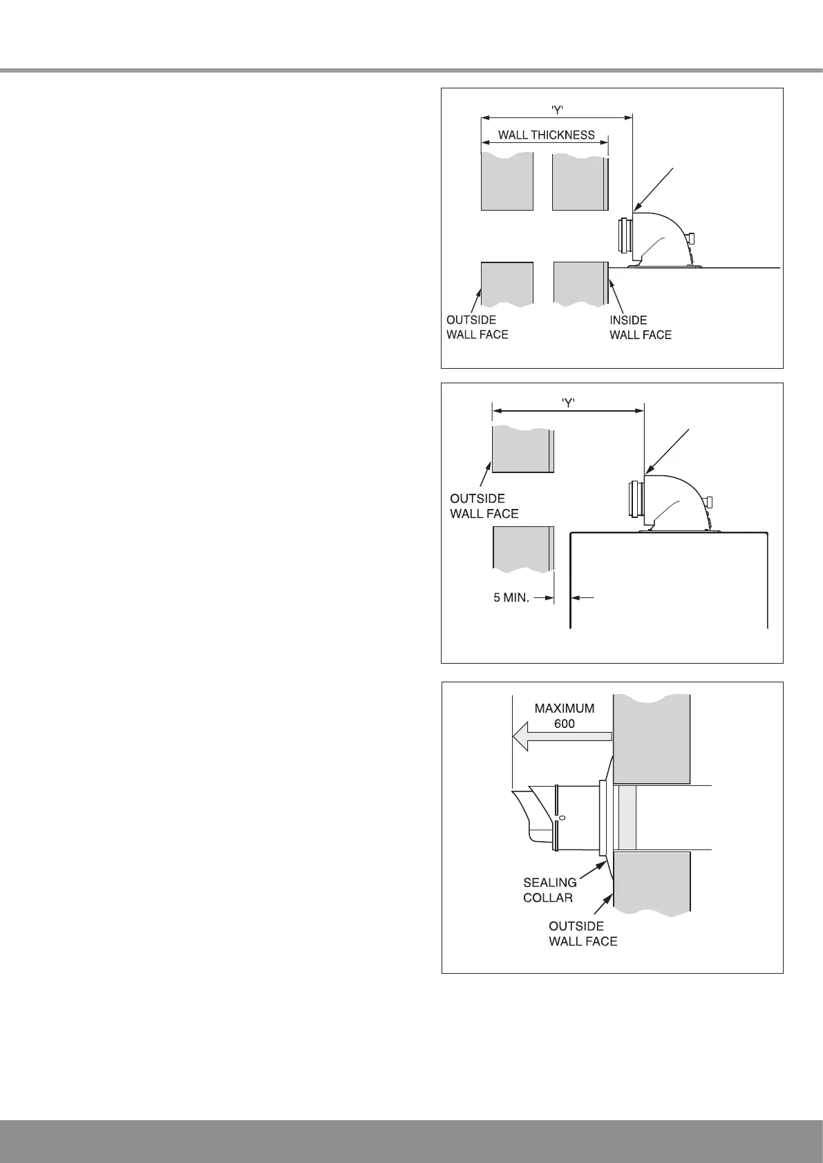
10.3 REAR Flue
If a wall thickness is between 233mm min. to 522mm max.
then the flue can be used without extensions.
With the flue elbow temporarily fitted, measure the distance
from the outside wall to the butt joint, see diagram
10.4. If
the measurement ‘Y’ exceeds 522mm, then the appropriate
length of extension pipe is required.
If the dimension is less than 320mm DO NOT cut the flue, it
can project to a maximum of 600mm, if this is not desirable
then a Standard flue MUST be used and cut to length.
10.4 SIDE Flue
With the flue elbow temporarily fitted, measure the distance
from the outside wall to the butt joint, see diagram 9.6. If the
measurement ‘Y’ exceeds LH 204mm, RH 417mm, then the
appropriate length of extension pipe is required.
If the dimension is less than 320mm DO NOT cut the flue, it
can project to a maximum of 600mm, if this is not desirable
then a Standard flue MUST be used and cut to length.
10.5 Flue Fitting
With the air duct seams aligned and the flue set to the
required length ‘Y’, mark the securing hole position in the air
duct. Drill a 3mm diameter hole at this position, take care not
to pierce the inner flue duct. Secure with screw provided and
tape the joint, see diagram 10.7.
Fit the sealing collar onto the locating ring on the flue
terminal, see diagram 10.8.
With the flue elbow removed, push the flue assembly into
the wall, externally or internally, until the end of the assembly
protrudes a short way from the inside face of the wall. This
will enable the internal trim ring (if required) to be positioned
and allow the flue assembly to be drawn back up to the flue
elbow.
Secure the flue elbow in position on top of the boiler with four
torque headed screws supplied.
Draw the flue assembly from wall and engage the flue duct
into the elbow and butt fit between the air duct and flue
elbow.
Check the correct alignment of the flue.
Fit the securing collar in position, mark through two of the pre
drilled holes in the securing collar. Remove securing collar
and drill two 3mm diameter holes one in the elbow and one
in the air duct, take care not to pierce the inner flue duct. Fit
the securing collar and secure with screws provided, see
diagram 10.9.
Slide the internal trim ring back against the wall, securing in
place with a small amount of sealant if required.
The cut ducts must be de-burred and all filings and debris
removed.
Insert the flue duct into the air duct terminal assembly,
remembering to engage the catch within the terminal.
NOTE: If the seals require lubricant to ease installation, do
not use mineral oils or grease, only silicon grease or water is
recommended.
Diagram 10.4
Diagram 10.6
12979
10 Telescopic Flue - Length, Preparation and Installation
Diagram 10.5
13224
13295

 Loading...


