45
13.4 Silencer
For access to the heat exchanger the silencer will need to be
removed, see diagram 13.7.
Remove the securing screw and pull the silencer from the gas
valve, this is a push fit.
13.5 Spark Electrode
Disconnect the ignition lead and two securing screws.
Withdraw the spark electrode carefully from the combustion
chamber, see diagram 13.8 and 13.9.
Inspect the tips for damage.
Clean away any debris and check the spark gap is 3.5 to 4.5
mm.
Check the electrode gasket for signs of damage and replace
if necessary.
NOTE: If the burner is not to be serviced, do not perform the
following instructions 13.6, 13.7 and 13.8 but continue to
section 13.9 to complete the servicing.
13 Servicing
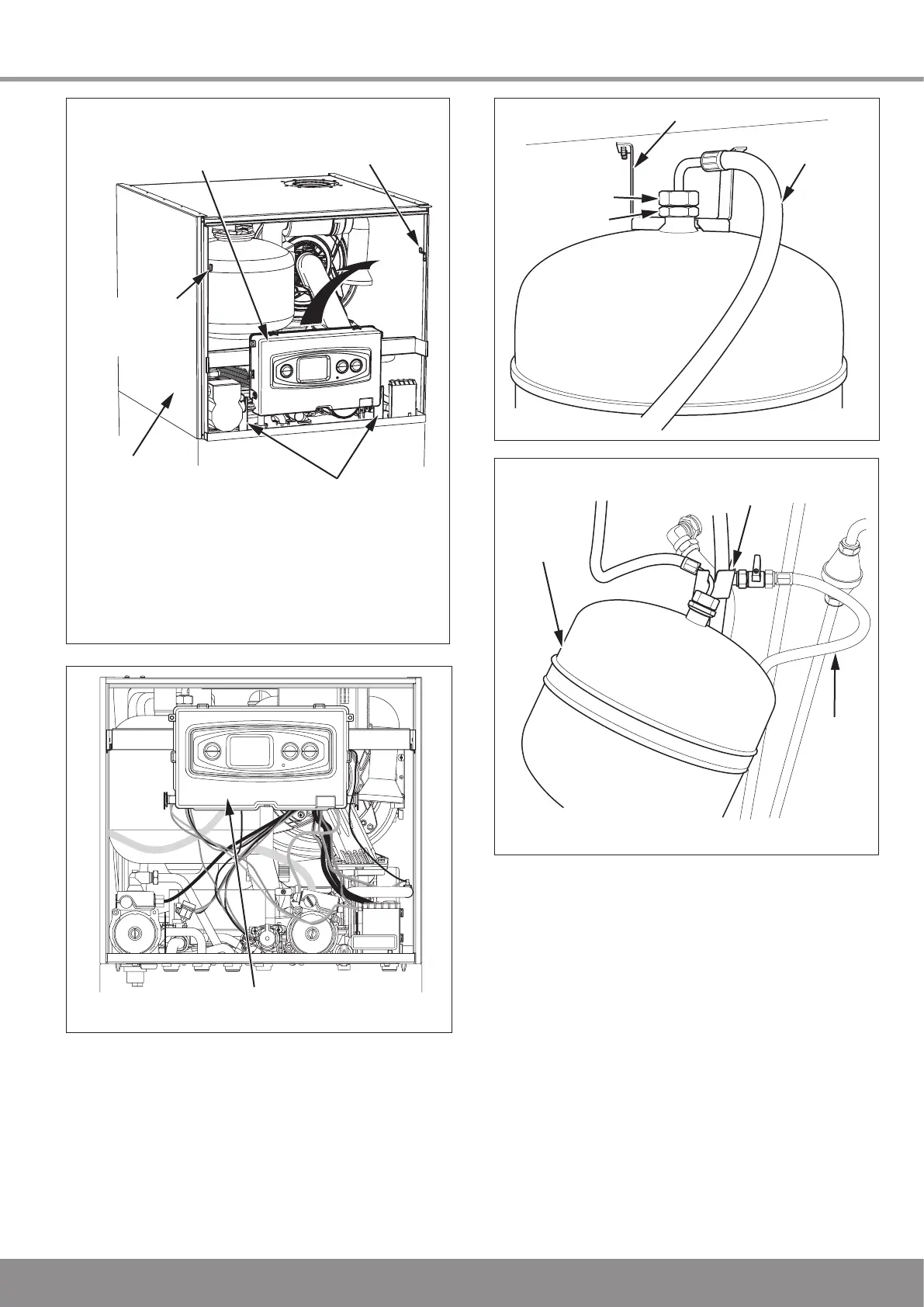
Diagram 13.4
13344
CONTROL BOX
MOUNTING BRACKETS
CONTROL BOX
SERVICE
BRACKET
*
CONTROL BOX
CONTROL BOX
SERVICE
BRACKET
* To move the control box into its service position
carefully pull the control box forwards and
upwards to release from its mounting brackets.
BOILER
MODULE
Diagram 13.3
13417
CONTROL BOX IN SERVICE POSITION
DOMESTIC
EXPANSION
VESSEL
SERVICE SUPPORT
BRACKET
SERVICE POSITION
FILLING
LOOP
13329
13330
DOMESTIC
EXPANSION VESSEL
FLEXIBLE
HOSE
BRACKET
UNION NUT
(Do not loosen)
LOCK NUT
Diagram 13.5
Diagram 13.6

 Loading...


