46
SECURING
SCREW
HEAT
EXCHANGER
SILENCER
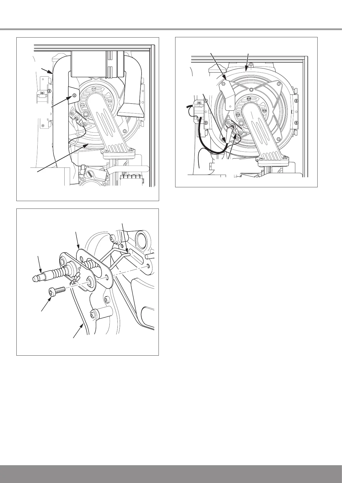
13.6 Burner
NOTE: If the functional checks did not indicate poor
combustion then it is not necessary to service the burner.
The following procedure will require that you replace the
burner door seal and nyloc nuts.
Slacken the gas connection at the union nut between the
boiler module and tank module.
Remove the gas supply pipe securing clip and withdraw the
gas pipe from gas valve, see diagram 13.10.
Disconnect the electrical connection at the gas valve and
disconnect the electrical connection from the fan.
Disconnect the ignition lead and earth lead from the burner
door, see diagram 13.9.
Disconnect the flue overheat thermostat, see diagram 13.11.
Remove the four burner door nyloc nuts, one of these also
holds the silencer bracket, see diagram 13.11.
Gently remove the fan, gas valve and burner assembly from
the combustion chamber, taking care not to trap the primary
return thermistor electrical cables.
Clean the burner with a soft brush taking great care not to
damage the front insulation. DO NOT use wire or sharp
instruments to clean the holes of the burner. Inspect the
burner for any signs of damage.
Remove and discard the burner door seal and replace with
new.
NOTE: Removal of the burner is not necessary during a
normal service, but If the burner has to be removed it will
require a new gasket when refitted, see diagram 13.12.
13343
Diagram 13.7
13 Servicing
ELECTRODE
GASKET
SPARK GAP
4mm
SECURING
SCREW
(2 OFF)
EARTH
LEAD
13273
Diagram 13.8
Diagram 13.9
13346
SILENCER
BRACKET
EARTH
LEAD
IGNITION
LEAD
HEAT
EXCHANGER

 Loading...


