47
13 Servicing
13.7 Heat Exchanger
NOTE: If the functional checks did not indicate poor
combustion then it is not necessary to service the heat
exchanger.
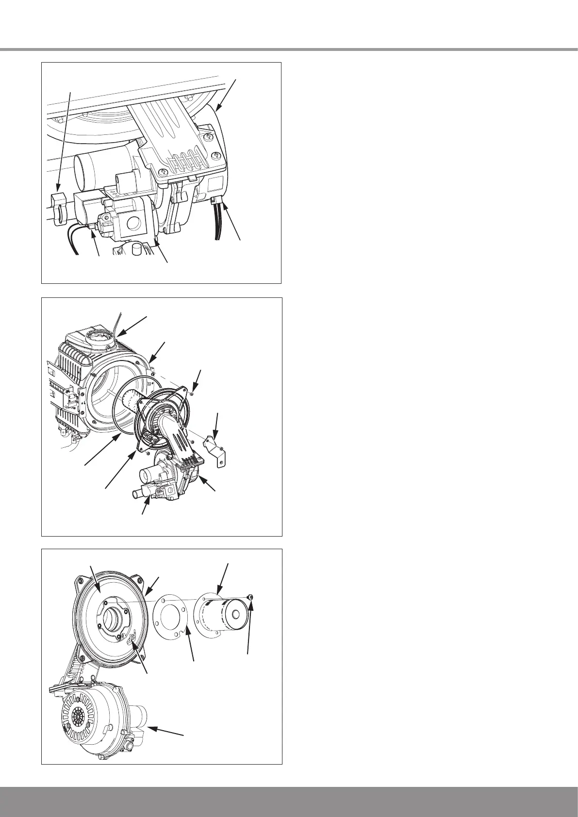
Refer to diagram 13.11.
Remove loose debris from inside the heat exchanger using a
soft brush and vacuum cleaner.
Carefully flush by spraying water into the heat exchanger, any
remaining debris should pass through the condensate trap
(Ensure the water is kept away from electrical components).
13.8 Combustion Setting
A combustion check should not be necessary unless a gas
carrying component has been replaced or the combustion
setting is suspect.
Connect a flue gas analyser to the sampling point, see
diagram 13.13.
IMPORTANT: Products of combustion will be discharged
when the cap is removed. It is important to replace the cap
immediately.
If no flue gas analyser is available and with the boiler module
front panel removed, check the flame picture through the
viewing window
Turn on the gas service cock, see diagram 12.1.
Turn on the electrical supply, the appliance will begin the
ignition sequence.
A competent person only should carry out any adjustment
to the gas valve, refer to diagram 13.14.
Monitor the combustion reading and at max rate the reading
should be 9.2% ± 0.5.
If adjustment proves necessary then proceed as follows:
Press the “reset” button on the controls fascia, release
and immediately press and hold in the “+” button. After
approximately 5 seconds “Hi” will be displayed.
Pressing the mode button when “Hi” is selected will force the
boiler to maximum rate, the display will flash between “Hi”
and the “default display” this will indicate the boiler has been
forced to maximum.
Adjust the maximum rate CO
2
with the throttle to 9.2%.
(Rotate anti-clockwise to increase).
To exit the check sequences press the “+” button, this will
reset the boiler to the default display.
ELECTRICAL
CONNECTION
GAS VALVE
FAN
ELECTRICAL
CONNECTION
GAS SUPPLY PIPE
SECURING CLIP
Diagram 13.10
13350 13356
BURNER
FRONT INSULATION
GASKET
SECURING
SCREW (4)
SPARK
ELECTRODE
GAS VALVE
AND FAN
BURNER
DOOR
Diagram 13.12
13373
NYLOC
NUT (4 OFF)
GAS VALVE
FA
N
BURNER
DOOR
SILENCER
BRACKET
SEAL
HEAT EXCHANGER
FLUE
OVERHEAT THERMOSTAT
Diagram 13.11

 Loading...


