5
D1030 - SIL 2 Switch / Proximity Detector Repeater Relay Output G.M. International ISM0008-17
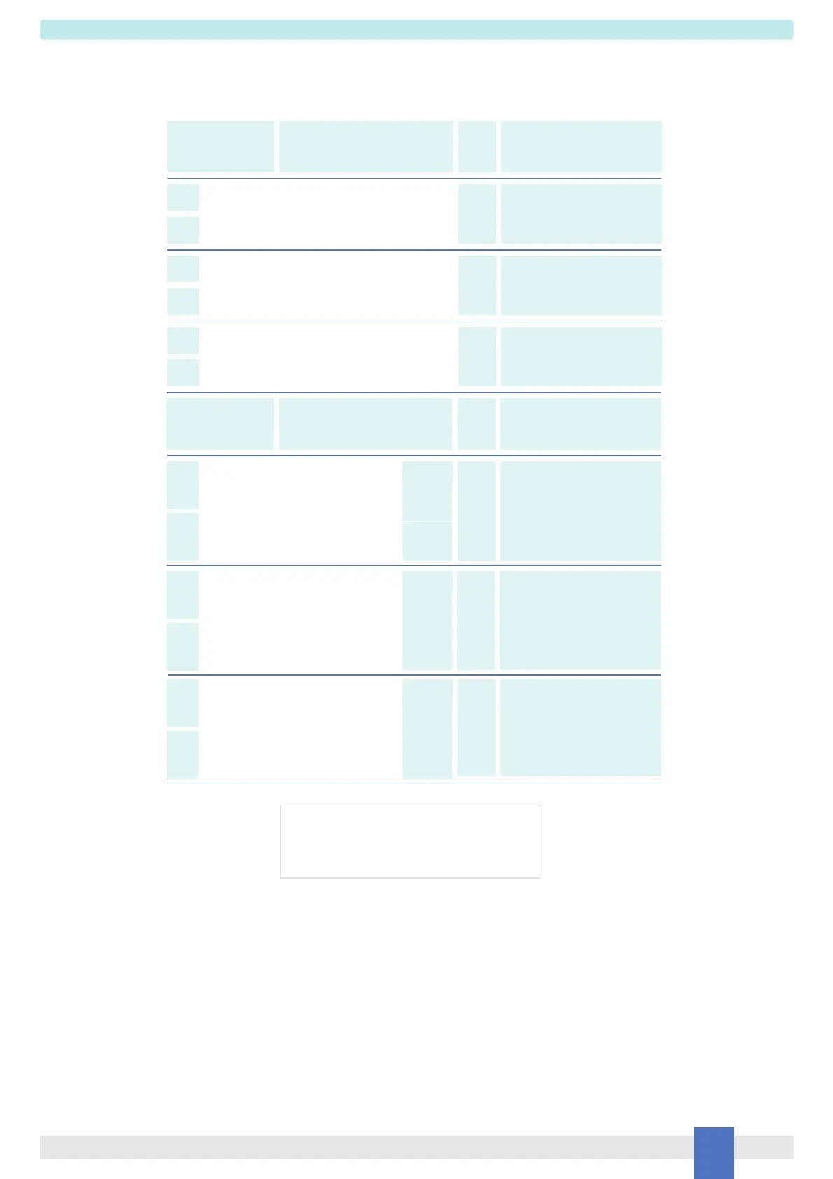
Parameters Table
In the system safety analysis, always check the Hazardous Area/Hazardous Locations devices to conform with the related system documentation, if the device is Intrinsically Safe check
its suitability for the Hazardous Area/Hazardous Locations and gas group encountered and that its maximum allowable voltage, current, power (Ui/Vmax, Ii/Imax, Pi/Pi) are not exceeded
by the safety parameters (Uo/Voc, Io/Isc, Po/Po) of the D1030 series Associated Apparatus connected to it. Also consider the maximum operating temperature of the field device, check
that added connecting cable and field device capacitance and inductance do not exceed the limits (Co/Ca, Lo/La, Lo/Ro) given in the Associated Apparatus parameters for the effective
gas group. See parameters on enclosure side and the ones indicated in the table below:
Must
be
Hazardous Area/
Hazardous Locations
Device Parameters
D1030 Associated
Apparatus Parameters
Must
be
Hazardous Area/
Hazardous Locations
Device + Cable Parameters
Uo / Voc = 10.7 V
Ui / Vmax
D1030 Terminals
Ch1
Ch2
13 -14
15 -16
Io / Isc = 15 mA
Ch1
Ch2
13 -14
15 -16
Po / Po = 39 mW
Ch1
Ch2
13 -14
15 -16
Ii/ Imax
Pi / Pi
D1030 Terminals
Ch1
Ch2
13 -14
15 -16
D1030 Associated
Apparatus Parameters
Ci / Ci device + C cable
Li / Li device + L cable
Li / Ri device and
L cable / R cable
IIC (A, B)
Co / Ca = 2.23 µF
Co / Ca = 15.6 µF
Co / Ca = 69 µF
IIB (C)
IIA (D)
IIC (A, B)
Lo / La = 172 mH
Lo / La = 689 mH
Lo / La = 1300 mH
IIB (C)
IIA (D)
IIC (A, B)
Lo / Ro = 930 µH/
Lo / Ro = 3720 µH/
Lo / Ro = 7440 µH/
IIA (D)
IIA (D)
NOTE for USA and Canada:
IIC equal to Gas Groups A, B, C, D, E, F and G
IIB equal to Gas Groups C, D, E, F and G
IIA equal to Gas Groups D, E, F and G
For installations in which both the Ci and Li of the Intrinsically Safe apparatus exceed 1% of the Co and Lo parameters of the Associated Apparatus (excluding the cable),
then 50% of Co and Lo parameters are applicable and shall not be exceeded (50% of the Co and Lo become the limits which must include the cable such that Ci device + C cable
50 % of Co and Li device + L cable 50 % of Lo). The reduced capacitance of the external circuit (including cable) shall not be greater than 1 F for Groups I, IIA, IIB and 600 nF for
Group IIC. If the cable parameters are unknown, the following value may be used: Capacitance 200 pF per meter (60 pF per foot), Inductance 1 µH per meter (0.20 µH per foot).
The Intrinsic Safety Entity Concept allows the interconnection of Intrinsically Safe devices approved with entity parameters not specifically examined in combination as a system when
the above conditions are respected.
For Division 1 and Zone 0 installations, the configuration of Intrinsically Safe Equipment must be FM approved under Entity Concept (or third party approved);
for Division 2 installations, the configuration of Intrinsically Safe Equipment must be FM approved under non-incendive field wiring or Entity Concept (or third party approved).
I
IIIC
I
IIIC
I
IIIC
Co / Ca = 60 µF
Co / Ca = 15.6 µF
Lo / La = 2263 mH
Lo / La = 689 mH
Lo / Ro = 12200 µH/
Lo / Ro = 3720 µH/
Ch1
Ch2
13 -14
15 -16
Ch1
Ch2
13 -14
15 -16
 Loading...