8
D1030 - SIL 2 Switch / Proximity Detector Repeater Relay Output G.M. International ISM0008-17
Functional Safety Manual and Application
Application for D1030S
Safety Function and Failure behavior:
D1030S is considered to be operating in Low Demand mode, as a Type B module, having Hardware Fault Tolerance (HFT) = 0.
The failure behavior is described from the following definitions, valid for each channel:
Fail-Safe State: it is defined as the channel output relay being de-energized (its NO contact is open and its NC contact is closed).
Fail Safe: failure mode that causes the module / (sub)system to go to the defined fail-safe state without a demand from the process.
Fail Dangerous: failure mode that does not respond to a demand from the process (i.e. being unable to go to the defined fail-safe state), so that the channel output relay remains
energized (its NO contact holds closed and its NC contact keeps open).
Fail Dangerous Detected: a dangerous failure which has been detected from module internal diagnostics so that channel output relay is forced to be de-energized (as Fail-Safe
state, with its NO contact is open and its NC contact is closed).
Fail “No Effect”: failure mode of a component that plays a part in implementing the safety function but is neither a safe failure nor a dangerous failure.
When calculating the SFF, this failure mode is not taken into account;
Fail “Not Part”: failure mode of a component which is not part of the safety function but which is part of the circuit diagram and is listed for completeness.
When calculating the SFF, this failure mode is not taken into account.
As the module has been evaluated in accordance with Route 2H (proven-in-use) of the IEC 61508:2010, Diagnostic Coverage DC 60% is required for Type B elements.
Being HFT = 0, in Low Demand mode the maximum achievable functional safety level is SIL 2.
Only Out 1-A is functional safety related, while Out 1-B (Pins 6-5 or 7-5) (as Duplicator of Out 1-A output) is only for service purpose, not functional safety related.
Failure rate data: taken from Siemens Standard SN29500.
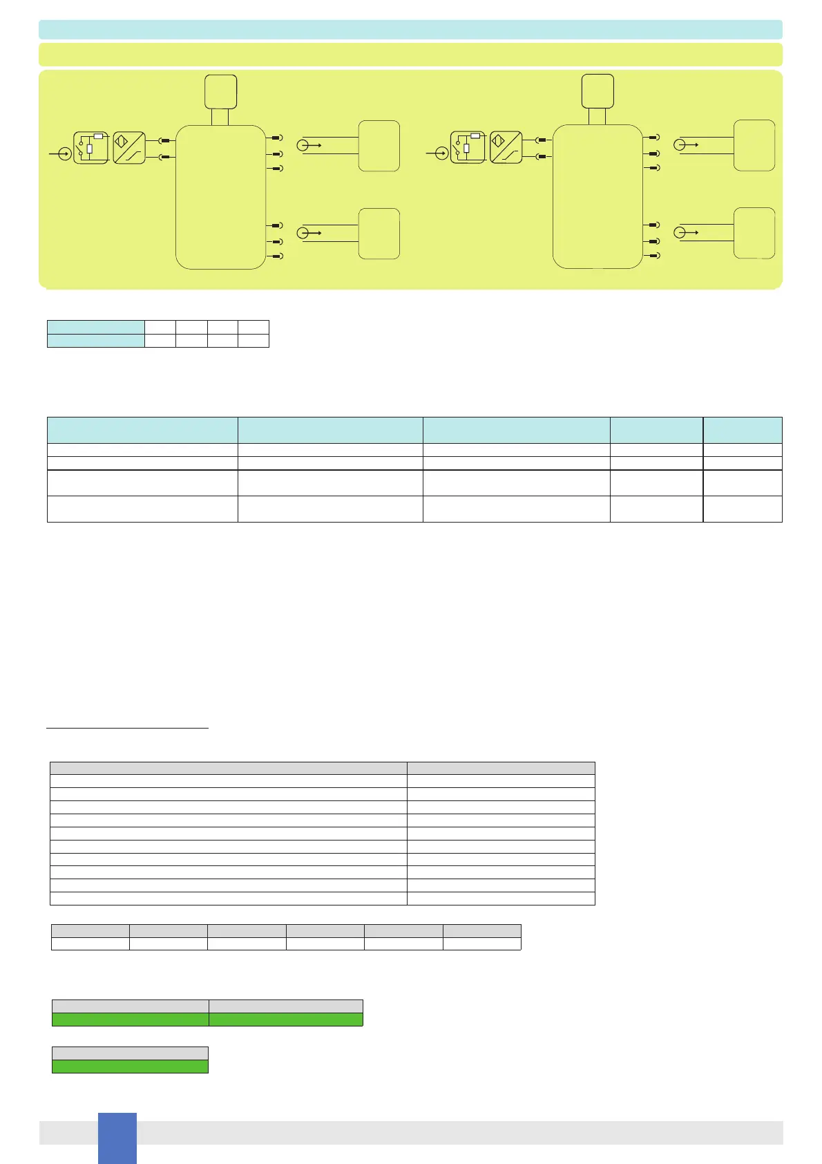
Description: For this application, enable input line fault (open or short) detection and direct input to output transfer function, by set the internal dip-switches in the following mode
(see page 12 for more information):
The module is powered by connecting 24 Vdc power supply to Pins 3 (+ positive) - 4 (- negative). The green LED is lit in presence of supply power.
Input signal from field is applied to Pins 13-14 (In 1 - Ch.1).
Only Out 1-A is functional safety related, while Out 1-B (Pins 6-5 or 7-5) (as Duplicator of Out 1-A output) is only for service purpose, not functional safety related.
The following table describes for Channel 1 the state (open or closed) of its output when its input signal is in OFF or ON state, and it gives information about turn-on or turn-off
of its channel status LED and channel fault LED:
Dip-switch position 1 2 3 4
ON/OFF state ON ON OFF -
Failure category Failure rates (FIT)
dd
= Total Dangerous Detected failures 73.09
du
= Total Dangerous Undetected failures 39.44
sd
= Total Safe Detected failures 0.00
su
= Total Safe Undetected failures 78.94
λ
tot safe
= Total Failure Rate (Safety Function) = λ
dd
+ λ
du
+ λ
sd
+ λ
su
191.47
MTBF (safety function, channel 1, Out 1-A) = (1 / λ
tot safe
) + MTTR (8 hours) 596 years
no effect
= “No Effect” failures 115.90
not part
= “Not Part” failures 65.92
λ
tot device
= Total Failure Rate (Device) = λ
tot safe
+ λ
no effect
+ λ
not part
373.29
MTBF (device) = (1 / λ
tot device
) + MTTR (8 hours) 306 years
λ
sd
λ
su
λ
dd
λ
du
DC
0.00 FIT 78.94 FIT 73.09 FIT 39.44 FIT 64.95%
SFF
79.40%
Failure rates table according to IEC 61508:2010 Ed.2 :
Failure rate table:
Input signal state
Pins 13-14 (In 1 - Ch.1)
Output relay contact state
Pins 2-1 (Out 1-A - Ch.1)
Proximity sensor is OFF or switch is open Open (De-energize relay)
Proximity sensor is ON or switch is closed Closed (Energized relay)
Independently from proximity sensor
or switch state, the input line is break
Open
(De-energized relay as safe state condition)
Independently from proximity sensor
or switch state, the input line is in short circuit
Open
(De-energized relay as safe state condition)
Channel status
yellow LED state
OFF
ON
OFF
OFF
Channel fault
red LED state
OFF
OFF
ON
ON
Output relay contact state
Pins 8-1 (Out 1-A - Ch.1)
Closed (De-energized relay)
Open (Energize relay)
Closed
(De-energized relay as safe state condition)
Closed
(De-energized relay as safe state condition)
D1030S
Field Input: proximity is OFF
or switch is open
Out 1-B is Out 1-A Duplicator
Channel 1
8
2
Out 1-A
Safety
PLC
Input
Supply
24 Vdc
3 +
4 -
13
14
In 1
1
Out 1-A relay is de-energized,
2-1 is open, 8-1 is closed
7
6
Out 1-B
PLC
Input
5
OFF operation
R1
R2
ON operation
D1030S
Field Input: proximity is ON
or switch is closed
Out 1-B is Out 1-A Duplicator
Channel 1
8
2
Out 1-A
Safety
PLC
Input
Supply
24 Vdc
3 +
4 -
13
14
In 1
1
Out 1-A relay is energized,
2-1 is closed, 8-1 is open
7
6
Out 1-B
PLC
Input
5
R1
R2
WARNING: R1 and R2 end of line resistors with voltage free contact are required for line fault detection
where DC means the diagnostic coverage for the input sensor by module internal diagnostic circuits. This type “B” system, operating in Low Demand mode with HFT = 0,
has got DC = 64.95 % 60 % as required by Route 2H evaluation (proven-in-use) of the IEC 61508:2010.
T[Proof] = 1 year T[Proof] = 5 years
PFDavg = 1.74 E-04 Valid for SIL 2 PFDavg = 8.70 E-04 Valid for SIL 2
PFDavg vs T[Proof] table (assuming Proof Test coverage of 99%), with determination of SIL supposing module contributes >10% of total SIF dangerous failures:
PFDavg vs T[Proof] table (assuming Proof Test coverage of 99%), with determination of SIL supposing module contributes 10% of total SIF dangerous failures:
T[Proof] = 10 years
PFDavg = 1.74 E-03 Valid for SIL 2
SC 2: Systematic capability SIL 2.
 Loading...