5
D5090-086 - 5 A SIL 3 Relay Output Module for NE Load G.M. International ISM0267-4
Functional Safety Manual and Applications
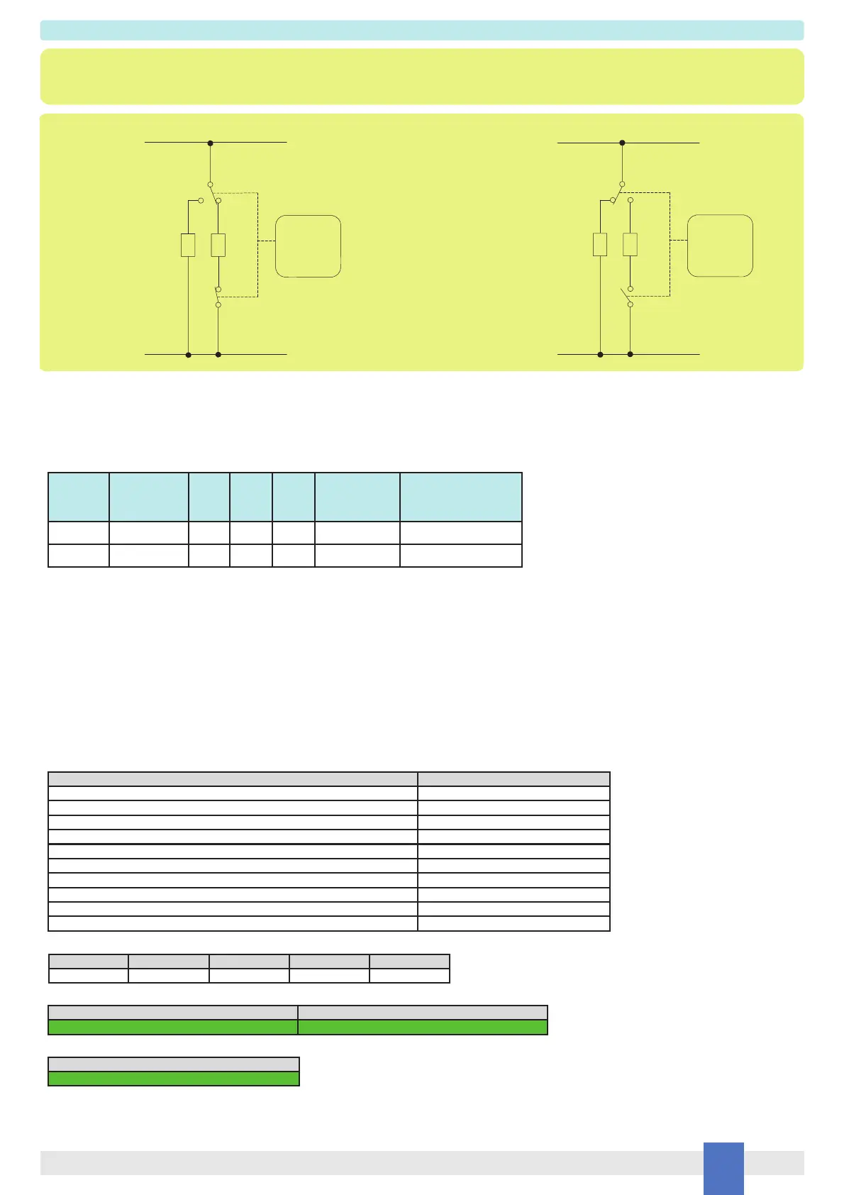
Normal state operation Energized to trip operation
9 - 7
10
11
PLC
Output OFF
0 Vdc
NE
Load
SIL 3
12
8
Service
Load
(Not SIL)
- / AC
+ / AC
9 - 7
10
11
PLC
Output ON
24 Vdc
NE
Load
SIL 3
12
8
Service
Load
(Not SIL)
+ / AC
- / AC
Description:
Input Signal from PLC/DCS is normally Low (0 Vdc) and is applied to pins 1-2 in order to Normally De-energize (ND) the internal relays.
Input Signal from PLC/DCS is High (24 Vdc) during “energize to trip” operation, in order to energize the internal relays.
The Load is Normally Energized (NE), therefore its safe state is to be de-energized; the Service Load is normally de-energized, therefore it energizes during
“energized to trip” operation.
Disconnection of the NE Load is done on both supply lines.
The following table describes the status (open or closed) of each output contact when the input signal is High or Low.
Safety Function and Failure behavior:
D5090S-086 is considered to be operating in Low Demand mode, as a Type A module, having Hardware Fault Tolerance (HFT) = 0.
In the 1st Functional Safety application, the normal state operation of relay module is de-energized, with NE (Normally Energized) load.
In case of alarm or request from process, the relay module is energized (safe state), de-energizing the load.
The failure behaviour of the relay module is described by the following definitions:
□ fail-Safe State: it is defined as the output load being de-energized;
□ fail Safe: this failure causes the system to go to the defined fail-safe state without a process demand;
□ fail Dangerous: failure mode that does not respond to a demand from the process (i.e. being unable to go to the defined fail-safe state),
so that the output load remains energized.
□ fail “No effect”: failure mode of a component that plays a part in implementing the safety function but is neither a safe failure nor a dangerous failure.
When calculating the SFF this failure mode is not taken into account.
□ fail “Not part”: failure mode of a component which is not part of the safety function but part of the circuit diagram and is listed for completeness.
When calculating the SFF this failure mode is not taken into account.
Failure rate date: taken from Siemens Standard SN29500.
Failure rate table:
Failure rates table according to IEC 61508:2010 Ed.2 :
PFDavg vs T[Proof] table (assuming Proof Test coverage of 99%), with determination of SIL supposing module contributes ≤10% of total SIF dangerous failures:
PFDavg vs T[Proof] table (assuming Proof Test coverage of 99%), with determination of SIL supposing module contributes >10% of total SIF dangerous failures:
Systematic capability SIL 3.
Operation Input Signal
Pins 1-2
Pins
7/9- 11
Pins
8 - 12
Pins
7/9 - 10
NE Load (SIL3)
Pins 11-12
Service Load
(Not SIL)
Pins 10 — AC / - Supply
Normal Low (0 Vdc) Closed Closed Open Energized De-Energized
Trip High (24 Vdc) Open Open Closed De-Energized Energized
Failure category Failure rates (FIT)
λ
dd
= Total Dangerous Detected failures 0.00
λ
du
= Total Dangerous Undetected failures 3.28
λ
sd
= Total Safe Detected failures 0.00
λ
su
= Total Safe Undetected failures 96.00
λ
tot safe
= Total Failure Rate (Safety Function) = λ
dd
+ λ
du
+ λ
sd
+ λ
su
99.28
MTBF (safety function, single channel) = (1 / λ
tot safe
) + MTTR (8 hours) 1149 years
λ
no effect
= “No effect” failures 260.72
λ
not part
= “Not Part” failures 42.60
λ
tot device
= Total Failure Rate (Device) = λ
tot safe
+ λ
no effect
+ λ
not part
402.60
MTBF (device, single channel) = (1 / λ
tot device
) + MTTR (8 hours) 283 years
T[Proof] = 1 year T[Proof] = 6 years
PFDavg = 1.44 E-05 - Valid for SIL 3 PFDavg = 8.64 E-05 - Valid for SIL 3
T[Proof] = 20 years
PFDavg = 2.88 E-04 - Valid for SIL 2
Application D5090S-086 - SIL 3 Load Normally Energized Condition (NE) and Normally De-Energized Relay,
with interruption of both load supply lines
1)
λ
sd
λ
su
λ
dd
λ
du
SFF
0.00 FIT 96.00 FIT 0.00 FIT 3.28 FIT 96.70%
 Loading...