D5090-086 - 5 A SIL 3 Relay Output Module for NE Load G.M. International ISM0267-4
8
Start-up
Before powering the inputs of unit check that all wires are properly connected, also verifying their polarity. Check conductors for exposed wires that could touch each other causing
dangerous unwanted shorts. Enabling input, the “RELAY STATUS” yellow led must be lit and load circuit must be de-energized because relay output contacts (Out 1 and Out 2) are open.
Indeed, disabling input, the “RELAY STATUS” yellow led must be turned off and load circuit must be energized because relay output contacts (Out 1 and Out 2) are closed.
Configuration
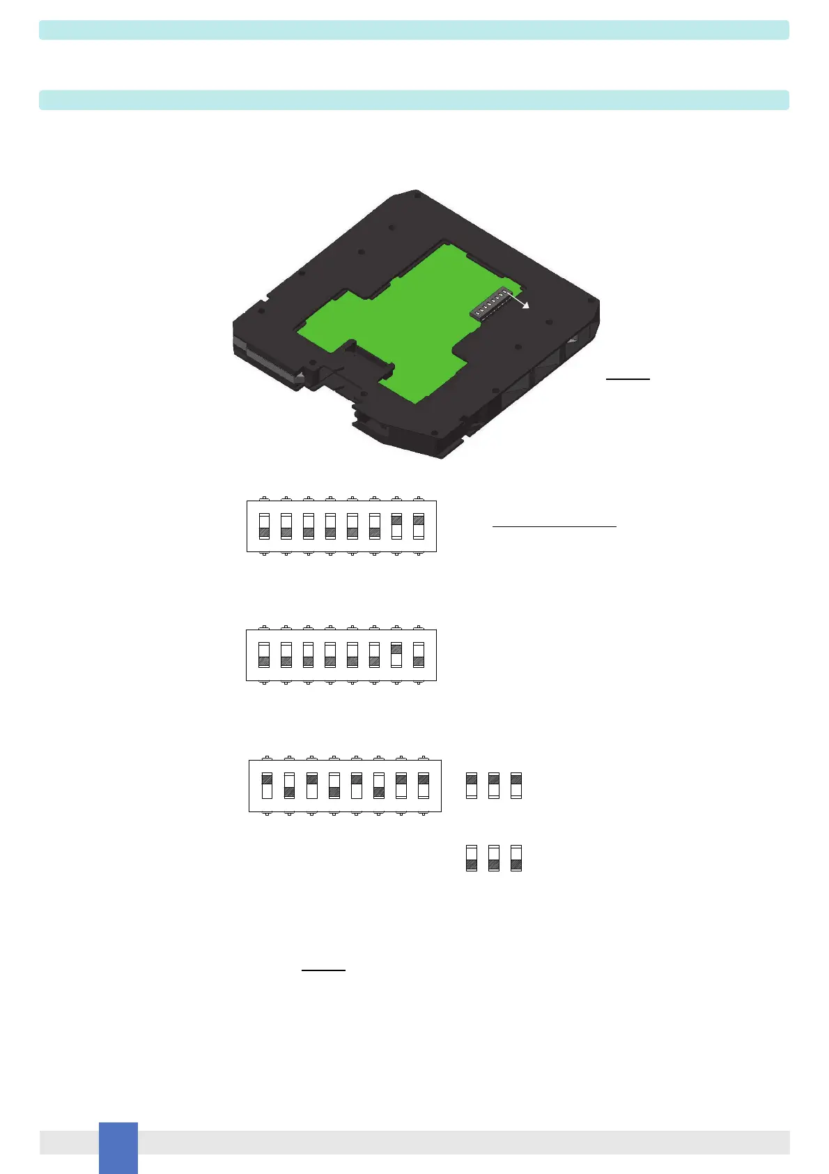
An eight position DIP Switch is located on component side of pcb in order to set four mutually exclusive configurations:
1) line input monitoring, to allow DCS/PLC line input monitoring function (driving line pulse testing);
2) low voltage input monitoring (UVLO—under voltage lock out): module reflects a high impedance state to the control unit when the driving voltage is below the specified threshold;
3) T-proof relay testing.
1) line input monitoring:
WARNING: after T-proof test, dip-switch 1-3-5 must be set to “OFF” position for normal operation.
2) low voltage input monitoring:
3) T-proof relay testing:
DIP switch configurations:
ON
123
45
6
7
8
ON
OFF OFF OFF OFF OFF OFF ON ON
12345678
ON
OFF OFF OFF OFF OFF OFF ON OFF
T-proof relays enable
135
13
5
Normal Operation
ON ON
OFF
ON
OFFOFF
T-proof relays (dip1 = relay1;
dip3 = relay2; dip5 = relay3)
12345678
ON
ON OFF ON OFF ON OFF ON ON
Please, see previous page for testing procedure at T-proof.
This is factory settings
WARNING: dip-switch 2-4-6
must be set to “OFF” position
for any configuration.
 Loading...