ADJUSTING BELT TENSION
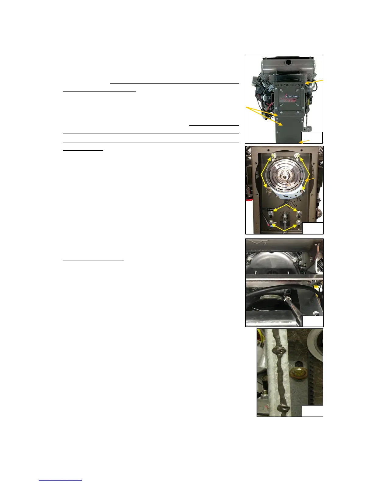
1. To adjust the belt, remove the top panel and two
lower panels shown in Fig. 1. The lower panels are
sealed with Loctite 598 High Performance RTV
Silicone Gasket Maker. The panel will need to be pried
from the frame with a large screwdriver. (Fig. 1)
2. Loosen all eight frame housing bolts. (Fig. 2 has the
brake plate removed so you can see the bolts easier. It
is not necessary to remove the brake for belt
adjustment.) The top set of 3 bolts go into the back of
the engine. Loosen the two top bolts with the universal
joint, 6” extension, and 5/8” socket. (Fig. 3) The bottom
four hold the engine plate onto the frame. The lower
right of that set is a stud with a nut welded on it. It is a
lot easier to use an 11/16” crowfoot wrench on this bolt
but an open-end wrench can be used. Adjust the nuts
on the vertical 3/8” x 6” bolt to tighten the belt. Move
about 1/2 turn on the nut and recheck tension. Repeat
until desired tension is reached. When tension is
reached tighten all eight frame bolts to 250 in.-lbs. (21
ft.- lbs.) and recheck tension again. If it is too tight or
too loose adjust again.
3. NEW BELT ONLY - If installing a new belt, loosen the
lower adjustment nut and turn the Upper adjustment
nut clockwise to loosen the belt. Remove all four of the
3/8” bolts securing the sprocket shaft bearing housing
shown on page 12. The sprocket unit can then be lifted
enough to change the belt. Reinstall them with the new
belt in place around the sprocket. Torque all four bolts
to 250 In.-Lbs. (21 Ft.-Lbs.)
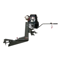
4. Remove all existing RTV Silicone from frame and
access panel and insure that mating surfaces are clean.
Apply a continuous 1/8” bead of silicone to the frame
surface and inside the bolt holes. Ensure that the bead is
continuous around the perimeter to prevent water leakage.
(Fig. 4)
5. Install the Access Panel and lightly tighten the 1/4” bolts.
Allow Silicone to cure for several hours and then torque all
bolts to 125 In.Lbs. (10Ft.- Lbs.)
6. After running your engine for the first time after sealing the
lower cover plates, remove the frame drain plug next to the
shaft housing to check for any water leakage. If any water
come out of the drain plug, you need to remove the lower
cover plates and re-seal it.