[page 12] | gpelectric.com
8. WIRING DIAGRAM
4. Disconnect one or both array wires from the controller. Take a voltage reading between the positive and negative array wire. A
single 12 volt module should have an open circuit voltage between 17 and 22 volts. If you have more than one solar module, you
will need to conduct this test between the positive and negative terminals of each module junction box with either the positive
or the negative wires disconnected from the terminal.
Remedy:
1.
Reconnectincorrectconguration.Tightenallconnections.Checkwiregaugeandlengthofwirerun.RefertoSuggestedMinimum
Wire Gauge in Section 4.
2. Clean modules, clear obstruction or wait for conditions to clear.
3. Iftheopencircuitvoltageofanon-connected12voltmoduleislowerthanthemanufacturer’sspecications,themodulemaybe
faulty. Check for blown diodes in the solar module junction box, which may be shorting the power output of module.
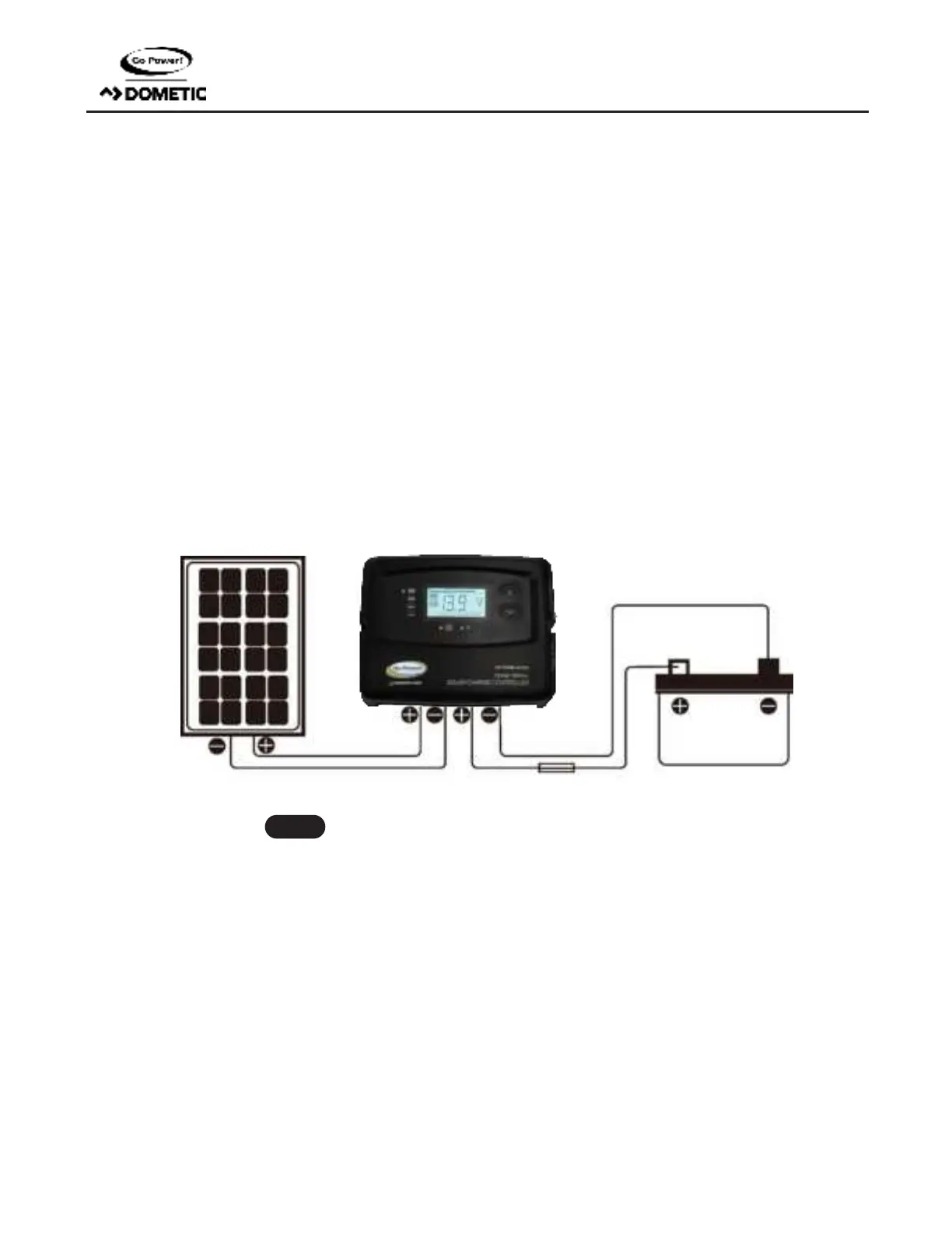
8. WIRING DIAGRAM
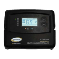
The GP-PWM-10-SQ is based on a 10 amp max input from the solar modules. Use the wiring diagram to connect your battery to the
battery terminals on the solar controller. First, connect the battery to the controller and then connect the solar panel to the controller.
The controller will not work unless there is a battery connected to the battery terminals.
Solar Panel +
Solar Panel –
Battery +
Battery -
The fuse or breaker used should be no larger than 10 amps.
Note
10 AMP Fuse
 Loading...