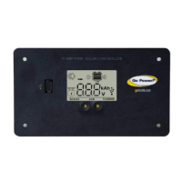
Do you have a question about the Go Power GP-PWM-10-FM and is the answer not in the manual?
| Rated Current | 10A |
|---|---|
| Nominal System Voltage | 12V |
| Maximum Solar Array Voltage (Voc) | 25V |
| Maximum Input Voltage | 25V |
| Display | LED |
| Self Consumption | < 10mA |
| Charging Algorithm | PWM |
| Type | PWM |
| Battery Type | AGM, GEL, Flooded, Lithium |
| Protection | Reverse Polarity, Overload, Short Circuit |
| Dimensions | 139 x 76 x 38 mm (5.5 x 3 x 1.5 in) |
Explains the role of a solar controller in a photovoltaic system.
Details the nominal system voltage, input current, and voltage ratings.
Lists the compatible battery types for the GP-PWM-10-FM.
Describes the automatic USB port shutoff when battery voltage is low.
Lists regulatory compliance marks (CE, RoHS).
Provides model, voltage, current, dimensions, wire gauge, and warranty details.
Outlines crucial safety measures for battery handling, wiring, and operational limits.
Lists the required tools and materials for installation.
Details criteria for mounting the controller, such as proximity to battery and surface type.
Instructions on using the template and marking mounting holes.
Guidance on installing solar modules, referencing kit instructions if applicable.
Recommends wire type, gauge, and strip length, including a gauge chart.
Instructions on connecting solar array and battery wiring to the controller.
Specifies torque values for terminal screws and advises re-torqueing after 30 days.
Instructions for physically mounting the controller and setting the correct battery type.
Presents a schematic diagram for wiring the solar controller, battery, and solar array.
Describes the controller's behavior upon initial power connection.
Details the procedure for selecting the appropriate battery charging profile.
A chart detailing charging parameters for different battery types.
Explains the automatic equalize feature for battery reconditioning.
How to navigate and view different data on the controller's display.
Instructions on how to reset the accumulated ampere-hour count.
Identifies and explains 'Over Voltage' and 'Low Voltage' error indicators.
Addresses common questions and potential issues users might encounter.
Covers battery water loss, gas emission, SOC not reaching 100%, and voltmeter discrepancies.
Troubleshoots blank/nighttime displays and explains warning signal triggers.
Addresses inaccurate voltage, overvoltage, zero, and low current readings.
Explains the meaning of various symbols displayed on the controller.
Information about the USB charging port, its capabilities, and limitations.
Outlines the terms, conditions, and exclusions of the product's limited warranty.
Lists common scenarios that void the warranty, such as misuse, improper installation, and acts of nature.
Provides contact information and steps for troubleshooting and product return.
Refers to a template on page 27 for flush mounting the controller.