GP-PWM-10-FM
12
© 2018 Go Power!
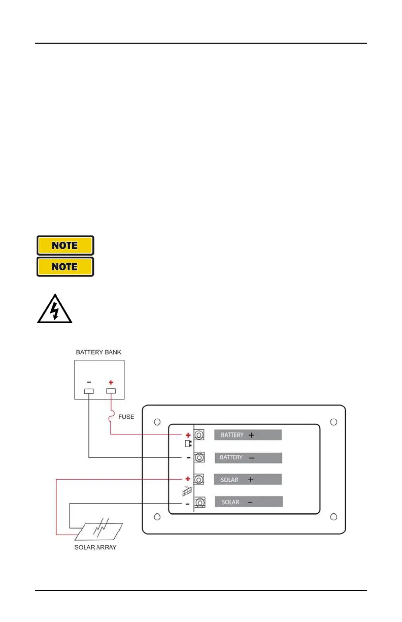
6.0 Wiring Diagram
IMPORTANT: This diagram is valid only for version 1.5 and newer.
Version 1.4 and older have different terminal locations.
The GP-PWM-10-FM Maximum 12.5A rating is based on a 10 amp total
maximum short circuit current rating (Isc) from the parallel solar modules
nameplate ratings. The National Electric Code specifies the PV
equipment/system rating to be 125% of the maximum Isc from the PV
module nameplate ratings (1.25 times 10 = 12.5A). Use the wiring
diagram (below) to connect your battery to the battery terminals on the
solar controller. First, connect the battery to the controller, and then
connect the solar panel to the controller.
The fuse or breaker used should be no larger than 15 amps.
The controller will not work unless there is a battery
connected to the battery terminals with at least 9V.
WARNING: When the photovoltaic (solar) array is exposed to
light, it supplies a dc voltage to this equipment
 Loading...