The Go Power! Remote Display (GP-RVC-R) is a user manual for the RVC10A and RVC30A solar controllers, designed to provide remote monitoring and control capabilities. This device is compatible with GP-RVC-30-MPPT and GP-RVC-10-MPPT Solar Controllers.
Function Description
The GP-RVC-R remote display allows users to monitor the status of their solar controller and battery banks, view detailed system information, adjust settings, and issue commands. It provides real-time data on PV voltage and current, battery voltage and current (for up to two battery banks on the 30A model), internal temperature, charge state, and fault conditions. The device also features Bluetooth® wireless technology, enabling live status monitoring and settings configuration via the Go Power! Connect App on Android and iOS mobile devices.
Important Technical Specifications
Display:
Controls:
- Back Button
- Enter Button
- Down Button
- Up Button
Connectivity:
- RJ12 Connectors for wired connection to the solar controller.
- Bluetooth® wireless technology for mobile device connectivity.
Compatibility:
- GP-RVC-30-MPPT Solar Controller (supports dual battery banks, BAT1 and BAT2 parameters).
- GP-RVC-10-MPPT Solar Controller (supports single battery bank, no BAT2 parameters).
Power Information Displayed:
- PV Voltage and Current
- Battery Voltage and Current (BAT1, BAT2 for 30A model)
- Total Watt Hours (Total WH)
- Total Amp Hours (Total AH)
- Daily Amp Hours (Ah Today, Ah 1 Day Ago, Ah 2 Day Ago, Ah 3 Day Ago)
System Status Displayed:
- Charge State (CHG STA): IDLE, Charging:Bulk, Charging:Absorb, Charging:Float, Charging:Equalizing
- Fault Conditions: PV:Reverse, PV:OVP, BAT:Reverse, BAT:War, BAT:UVP, BAT:OVP, BAT:NC
- Battery Temperature (Battery Temp)
- Device Temperature (Device Temp)
- Run Time (number of days controller has been operating)
Firmware/Hardware Information:
- FW Ver (Firmware Version)
- HW Ver (Hardware Version)
- SN Num (Serial Number)
- Type (Controller type, e.g., GP-RVC-30)
Mounting:
- Intended for interior wall mounting.
- Requires a 1" (25.4mm) diameter hole for cable routing.
- Mounting screw spacing: 4.1" (105mm).
Usage Features
Startup Screens:
- [MENU 1]: RVC-DISPLAY Establishing connection with the controller.
- [MENU 2]: RVC-DISPLAY startup, displays "Go Power!".
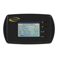
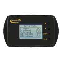
Main Screen [MENU 3]:
- Displays PV Voltage, Current, BAT1 and BAT2's Voltage and Current, Solar Controller Internal Temperature, Solar Controller Charge State / Fault, and Bluetooth Connection Status.
- The 10A controllers only show BAT parameters, not BAT1 and BAT2.
Status Screens [MENU 4] to [MENU 8]:
- Accessed by a short press of the [ENTER] button from the main screen.
- Navigation:
- [DOWN] button: cycles through menus in sequence (MENU4 -> MENU5 -> ... -> MENU8 -> MENU4).
- [UP] button: cycles through menus in reverse sequence (MENU8 -> MENU7 -> ... -> MENU4 -> MENU8).
- Exit: [BACK] button returns to the main interface.
- Provide detailed status information not shown on the main screen, such as Chg Current, Battery Temp, Device Temp, Fault, Run Time, Total WH, Total AH, daily AH logs, Solar Rated V, Batt Rated V, Batt Rated I, FW Ver, HW Ver, SN Num, and Type.
Setting Screens [MENU 9] to [MENU 16]:
- Accessed by a long press of the [ENTER] button from the main screen.
- Navigation:
- [DOWN] button: moves down one setting (cursor wraps to top).
- [UP] button: moves up one setting (cursor wraps to bottom).
- Editing Settings:
- Press [ENTER] on a setting to enter edit mode (value flashes).
- Use [DOWN] and [UP] buttons to change the value.
- Press [ENTER] to lock the new setting.
- Press [BACK] to cancel changes.
- Exit: [BACK] button returns to the main interface.
- Settings include:
- Basic Settings: I Limit (Charging Current Limit).
- Battery Type Settings: Type (Flooded, GEL, AGM, Li, USER), Nom V (System Voltage - AUTO, 12V, 24V), AH (Capacity).
- Advanced Settings: OVP (High Voltage Disconnect), Eq V (Equalization Voltage), Bulk V (Bulk-Absorption Voltage), Float V (Float Voltage), Chg Rtn (Recharge Voltage), LRV (Over-discharge return), Warn V (Under Voltage Warning), ODV (Discharge Limit Voltage), Batt1 ODVD (Bank 1 Over-discharge Delay Time), Equ Time (Equalization Duration), BST Time (Absorption Duration), Equ Int (Equalization Interval), T Comp (Temp Comp Factor).
- Dual Bank Settings (30A model only): Batt2 I Limit, Batt2 Type, Batt2 Nom V, Batt2 Ah, Batt2 OVP, Batt2 Eq V, Batt2 Bulk V, Batt2 Float V, Batt2 Chg Rtn, Batt2 LRV, Batt2 Warn V, Batt2 ODV, Batt2 ODVD, Batt2 Eq Time, Batt2 BST Time, Batt2 Eq Int, Batt2 T Comp.
Commands:
- Force CHG: Forces the controller into either bulk or float charge stage for either battery bank (1 or 2 for 30A model). Options: Normal, Main Bulk, Main Flt, Alx Bulk, Alx Flt.
- Set Defaults: Resets all configurable parameters to factory defaults.
- Clear History: Resets historical data.
Bluetooth Wireless Technology:
- Enables live status monitoring and settings configuration via the Go Power! Connect App.
- Pairing process: Initiate pairing on the remote, then select the remote in the app's Device Selection page.
- SOC Indication: Visual battery level indicator on the app, corresponding to specific battery voltage ranges (12V/24V system).
Maintenance Features
Product Packaging:
- Users are advised to safely store the original packaging or recycle its components (corrugated fiberboard, plastic foam protection, LDPE plastic accessories bag) as outlined in the manual. Recycling information is provided via www.earth911.com/recycling-center-search-guides.
Warranty:
- A five (5) year limited warranty covers defects in materials and workmanship from the date of shipment.
- Warranty is voided by misuse, abuse, neglect, accident, exceeding design limits, improper installation, acts of God, handling damage, or if the unit is opened, altered, or its serial number is removed/defaced.
Repair and Return Information:
- Troubleshooting: Users are directed to the "frequently asked questions" section on gpelectric.com/support/.
- Support Contact: Online Contact Us form, Live Chat, or email techsupport@gpelectric.com.
- Returns: Defective products should be returned to the place of purchase.
Safety Precautions:
- The manual emphasizes important safety information, categorized as "Warning" (bodily harm) and "Caution" (property damage).
- Symbols indicate specific hazards: General Warning, Hot Surface, Risk of Shock, Risk of Fire, Risk of Electrocution, Risk of Chemicals, Risk of Explosion, Risk of Eye Injury.
- Key safety instructions include:
- Disconnect all power sources before installation.
- Observe battery manufacturer's safety precautions (batteries produce explosive hydrogen gas).
- Ensure all wiring connections are tight and secure to prevent sparks and heat.
- Wear protective eyewear and appropriate clothing during installation.