gpelectric.com | [page 11]
3. PLANNING LOCATIONS
3.1 PLAN YOUR SOLAR SYSTEM SETUP
1. Take a few minutes before commencing any installation work to layout your solar system on paper rst. Use the diagrams
within this manual (pages 20-27) to help.
2.
Complete a simple block diagram identifying the key components and connections of your Solar charging system: Solar
Panels, MC4 Positive and Negative Extension Cables, GP-PWM-30 Solar Charge Controller and your Battery Bank as
detailed in the diagrams.
3.
For the Elite and Extreme Kits include the Inverter, Charger/Converter and Transfer Switch. For detailed installation of
these system components see the specic manuals included with each item.
4. Identify and prepare easy/safe access to possible installation locations in the 3 key installation areas within your RV;
• Roof Solar Panels
• Instrument/Controls Solar Charge Controller and/or Inverter Remote
• Storage Compartments Inverter, Converter/Charger, Transfer Switch
5.
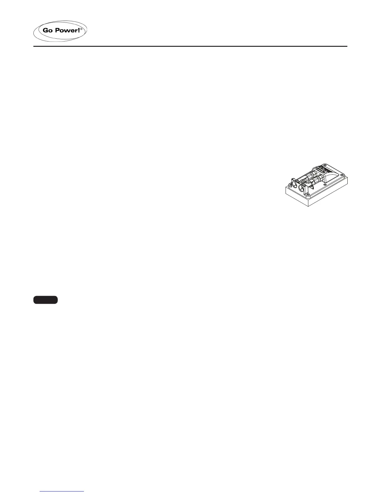
Identify on your RV if you have a Cable Entry Plate (CEP) see Fig 3-A pre-installed by the
RV Manufacturer. The Cable Entry Plate makes the Solar Panel to Solar Charge Controller
installation simpler. (After market purchase of GP-CEP available)
6.
If you do not have the Cable Entry Plate pre-installed on your RV, you will be following the
‘Routing Power Cable through the Refrigerator Vent’ steps.
7.
Whilst on the roof of your RV identify the refrigerator vent and investigate the vent-fastening
hardware.
3.2 PLACEMENT OF SOLAR PANELS
1. Remove all solar panels from their boxes. Set aside the boxes as they will be used in the instructions to follow.
2. Using the solar panel boxes, plan the layout of the panels on your RV rooftop. Once you have positioned the boxes
• Placement of the panel(s) should be as close together as possible. Each panel has 3.3’ of cable coming from the
junction box. It may be necessary to use solar panel extension cables. If required, longer extension cables can be
purchased. Please contact customer service at 1.866.247.6527 to purchase.
• Select a location where the mounting surface is at least 1/2” thick and strong enough to support the solar panel
mounting hardware.
• Solar panels should be located a minimum of 3’ from the front of RV to reduce wind load on the panels.
• Avoid internal wiring when selecting the solar panel mounting locations for drilling the mounting holes.
• Ensure xed obstacles, such as air conditioners, will not shade the solar panels. (Shading can greatly reduce the
performance of the solar system).
•
Ensure there is enough room to access the panels and other xed obstacles for future inspection and maintenance.
Note
FIGURE 3-A: CEP
 Loading...