[page 16] | gpelectric.com
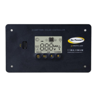
4.8 CONNECT THE GP-PWM-30 TO BATTERY BANK
It is recommended to connect directly to the battery whenever possible. You can also connect to the converter/charger where
the battery positive and negative wires connect to the converter/charger
1. Clean all corrosion from the battery terminals before proceeding
2. Crimp ring terminals onto the positive and negative cables to be attached to the battery
3. Check the ring terminal crimp connection by gently pulling on the cable and ring terminal
4.
Attach the Negative (Black) ring terminal to the battery bank and tighten according to the battery manufacturers specication
5. Attach the Positive (Red) ring terminal to the battery bank and tighten according to the battery manufacturers specication
6. Check all electrical connections
7. Apply a protective coating to the battery terminals
4.9 INITIAL CONNECTION AND OPERATING
1. Check all electrical connections and ensure all cables are securely fastened
2. Install the 30A Fuse into the fuse holder, ensure the fuse holder is securely fastened
3. Remove the opaque material from the solar panels
4. Follow the PWM 30 User Manual and operating steps
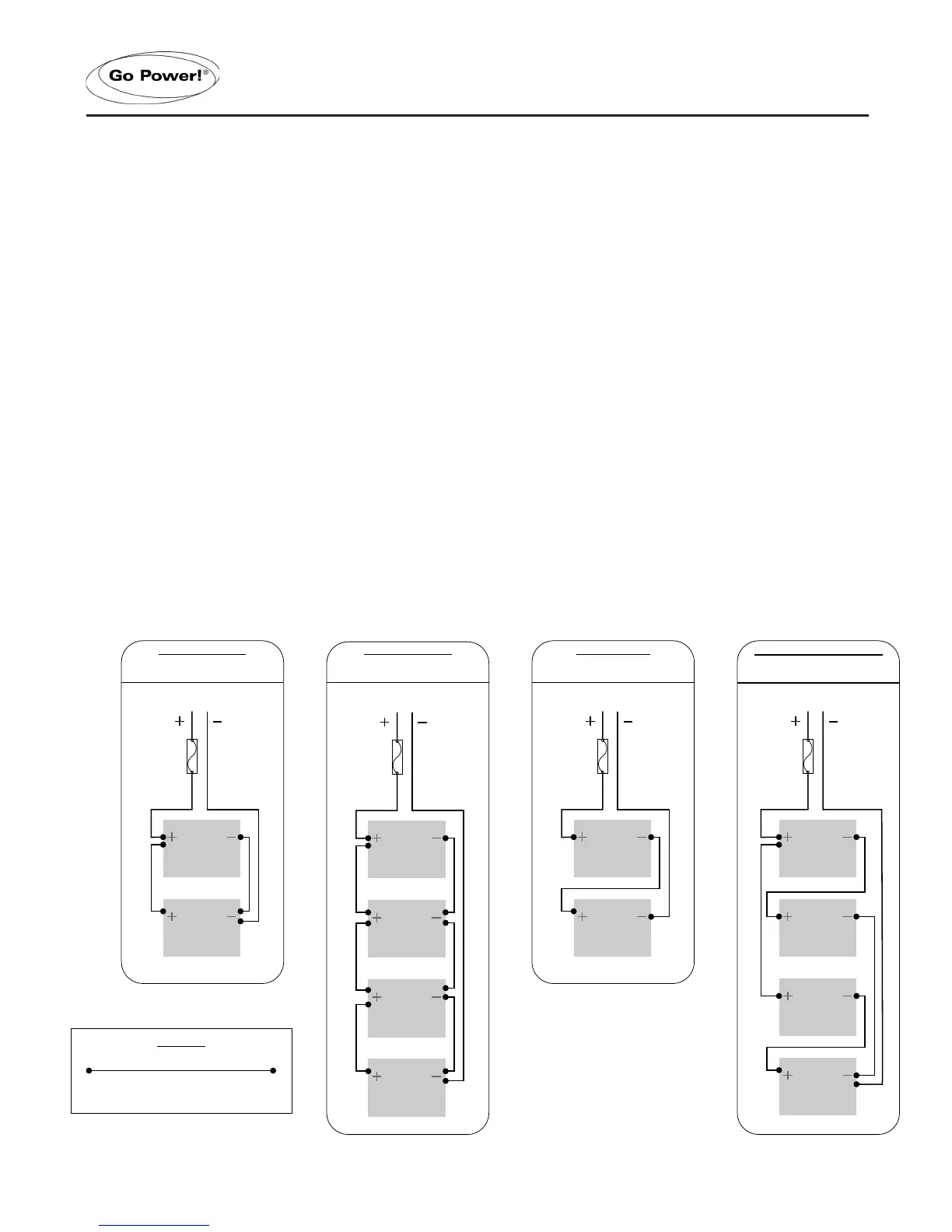
4.10 BATTERY BANK CONFIGURATIONS
INSTALLATION
System Voltage = 12V
System Capacity = 200A/Hr
Series & Parallel: 4 x 6V
System Voltage = 12V
System Capacity = 400A/Hr
System Voltage = 12V
System Capacity = 400A/Hr
System Voltage = 12V
System Capacity = 200A/Hr
FIGURE 4-J: TYPICAL BATTERY BANK CONFIGURATIONS
 Loading...