Do you have a question about the Go Power SOLAR EXTREME and is the answer not in the manual?
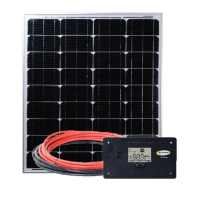
Explains how solar panels, batteries, and charge controllers interact to provide power.
Lists essential safety precautions for handling panels, batteries, and wiring during installation.
States manufacturer's liability limitations and recommends professional installation for safety and code compliance.
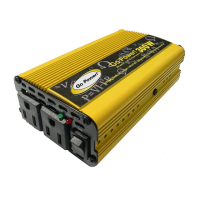
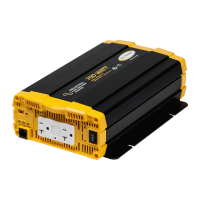
Lists all components included in various Go Power! RV solar kits with quantities for each model.
Details all necessary tools and equipment required for the successful installation of the solar charging kit.
Guides users on creating a system layout, identifying key components, and selecting installation areas within the RV.
Provides guidelines for optimal solar panel positioning on the RV roof for maximum sun exposure and structural integrity.
Details recommended indoor placement for the solar charge controller for monitoring, protection, and accessibility.
Instructions for assembling and attaching the mounting feet to the solar panels and securing them to the RV roof surface.
Steps for positioning panels on the RV roof, connecting extension cables, and applying sealant for a watertight installation.
Method for routing solar panel cables through a drilled hole in the RV refrigerator vent cover.
Method for routing solar panel cables through the RV refrigerator vent screen.
Procedure for connecting solar panel cables using a pre-installed RV Cable Entry Plate (CEP).
Step-by-step guide for mounting the solar charge controller indoors, including cutting and drilling requirements.
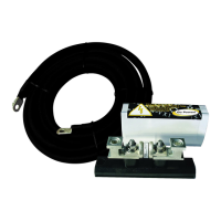
Instructions for installing the inline 30A fuse and fuse holder into the positive battery cable connection.
Procedures for securely connecting the charge controller to the RV battery bank, including terminal preparation.
Final steps before system operation: installing fuse, removing panel covers, and following controller manual.
Illustrates different battery connection methods (parallel, series) for various system voltages and capacities.
Recommends periodic checks of electrical and mechanical connections for looseness or damage after installation and transit.
Provides guidance on cleaning solar panels for optimal performance and visual inspection of the system components.
Advice on battery maintenance and solar system performance during long-term RV storage in different climate conditions.
| Input Voltage | 12V DC |
|---|---|
| Output Voltage | 120V AC |
| Continuous Power | 1500W |
| Surge Power | 3000W |
| Efficiency | 90% |
| THD | <3% |
| Frequency | 60Hz |
| Waveform | Pure Sine Wave |
| Protection Features | Overload, over temperature, short circuit |
| Power Output | 1500W continuous |