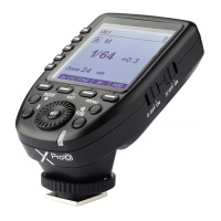
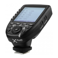
LCD Panel
(1) Multi Groups
Display
1. Channel (32) 2. Camera Connection 3. Modeling Lamp Master Control
4. High-Speed 5. Sound 6. Battery Level Indication 7. Group 8. Mode
9. Power 10. Group’s Modeling Lamp 11. ZOOM Value 12. Icons of Function Button
13. C.Fn Menu 14. Version
CH1
A
B
C
D
E
--
M
Zm/CH SYNC ALL
MOD
1/128
--
--
--
CH19
A
M
Zm/CH SYNC Gr
MOD
1/128
Zoom 35 mm
C.Fn
CLEAR
Ver 9.2
BEEP
MIN
LIGHT
STBY
ON
OFF
z
z
z
CH19
Zm/CH SYNC
MOD
Zoom 28
A
B
C
D
E
Zoom 24
Zoom 24
Zoom 24
Zoom 24
13 14 1111
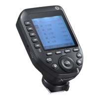
(4) Multi Groups’ ZOOM
Display
(2) Single Group
Display
(3) Menu
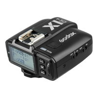
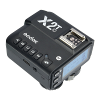
Names of Parts
3
CH1
A
B
C
D
E
--
M
1/16 + 0.3
--
--
--
Zm/CH SYNC ALL
MOD
1
7
8
6
9
4 5
10
12
32
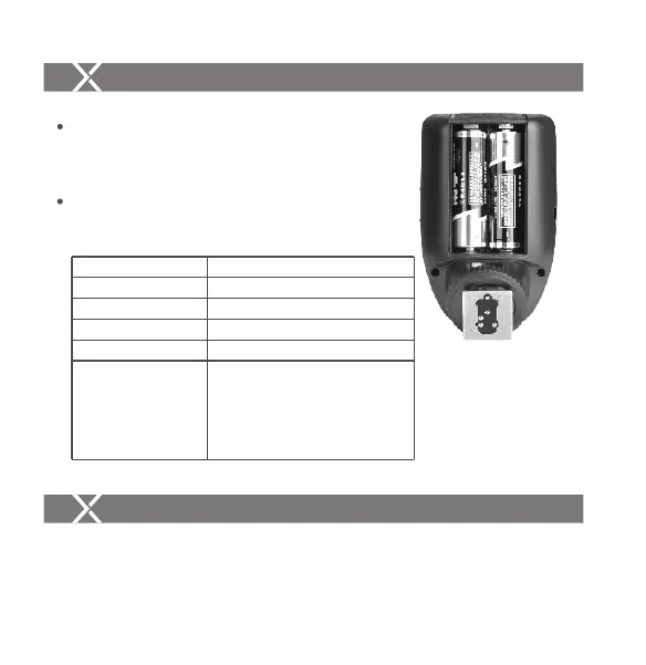
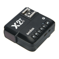
Installing Batteries
As shown in the illustration, slide the battery
compartment lid of the flash trigger and insert two
AA batteries separately.
Battery Level Indication
Check the battery level indication on the LCD panel
to see the remaining battery level during the usage.
Battery
AA alkaline batteries are recommended.
Battery Level Indication
3 grids
2 grids
1 grid
Blank grid
Blinking
Meaning
Full
Middle
Low
Low battery, please replace it.
< 2.5V The battery level is going
to be used out immediately (please
replace new batteries, as low power
leads to no flash or flash missing in
case of long distance).
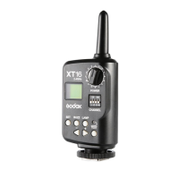
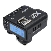
1.1 Turn off the camera and mount the transmitter on camera hotshoe. Then, power
on the flash trigger and the camera.
1. As a Wireless Camera Flash Trigger
Take TT685N as an example:
Using the Flash Trigger
The battery indication only refers to AA alkaline batteries. As the voltage of Ni-MH battery tends to be
low, please do not refer to this chart.
- 25 - - 26 -