ASSEMBLY OF THE PROBE
The probe is height-adjustable.
The probe may not be shortened
under any circumstances.
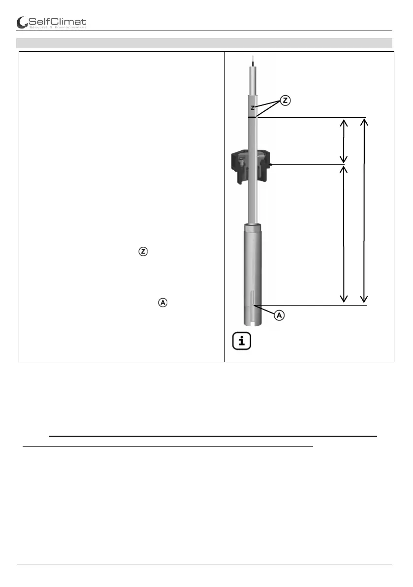
Adjusting dimension X
The adjusting dimension X is the distance
between the reference edge between the dome
cover or screw-in unit and the marking ring on the
protective cover of the sensor at the lower end of
the probe.
Control dimension Y
The control dimension Y results from the
difference between the probe dimension Z and
the adjusting dimension X. It represents the
distance between the upper marking line and the
reference edge of the dome cover or screw-in
unit. The probe is the part of the limit indicator
that protrudes into the tank in a height-adjustable
manner, which has a sensor (PTC thermistor as
temperature-dependent PTC resistor) protected
on the bottom.
Probe lengths from 150 to 1000mm are possible.
(Observe the tank permit!)
A marking line and a number have been
embossed into the top of probe tube. The marking
line and the value for Z must be visible upon
installation.
The number indicates the distance from the
marking line to the switching point (marking at
the bottom of the probe) in millimetres. Probes
with probe tube lengths Z = 500 to 1000mm: The
probe tube protruding from the tank is to be
protected from mechanical stress if necessary.
Insert the probe carefully and do not damage it!
The probe must be installed according to the assembly and operating manual and be set to
the maximum of the permissible filling volume with permissible filling level – generally
<95% (V/V) of the rated volume of the tank as well as according to the stipulations of the
building’s certificate of suitability for intended use for tanks or tank systems in the case of
battery tanks made of plastics. In case of tanks which are filled via an automatically closing
discharge valve, the filling is to be ended when an optical and acoustic alarm of the BC-1 is
given. In case of tanks/plants with installed signalling and control devices as well as signal
amplifiers as an overfill prevention divice, the following must be observed:
If the filler line is longer than 20m, the adjusting dimension X is to be determined according
to the special conditions. If necessary, contact the tank manufacturer with a specification of
the special tank shape and size, as well as the length of the filler line.
The criterion in this case is the overrun volume in the filler line which may not lead to an
exceeding of the maximum permissible filling volume.
If no information regarding the response height is available, the adjusting dimension X can
be determined by the volumetric measurement of the tank or by the calculation of the
response height according to the "Zulassungsgrundsätze für Überfüllsicherungen” of the
DIBt (see page 7). The connection lines between the probe and the indicator may have a
total length of a max. of 200m when a suitable cable with a cross-section of 2 x 1.5mm
2
(Cu)
is used.
Overfill prevention divice type BC-1
part no. 308 393 _15 700 71 a
 Loading...