Leak detector type LAG 2000 A
16 / 28 part no. 15 071 53 e
Installation dimension a for the LDL tank within the scope of replacing leak detectors
• The minimum installation dimension amin for replacing leak detectors within the scope of
TRbF 501 is to be determined according to calculation equations [5] and [6] and be
complied with. The installation dimension a
max
may not be exceeded and must be
determined according to calculation equation [4].
• The following applies: a
min
≤ a ≤ a
max
[1]
• Distance between the check valve and the bottom of the LDL tank: ≥ 10cm
The arrangement of the LDL tank for above-ground and underground tanks is shown
schematically in Figure 4.
Calculation equations for installation dimension a (scope a TRbF)
min
D x (
ρ
- 1) + p
o,1
+ 30
Calculation equation [5] applies only with [6]
Tabelle 7: The following changes compared to Table 6 (scope TRbF):
30 cm
Safety allowance
only for underground tanks
According to VdTÜV fact sheet 904
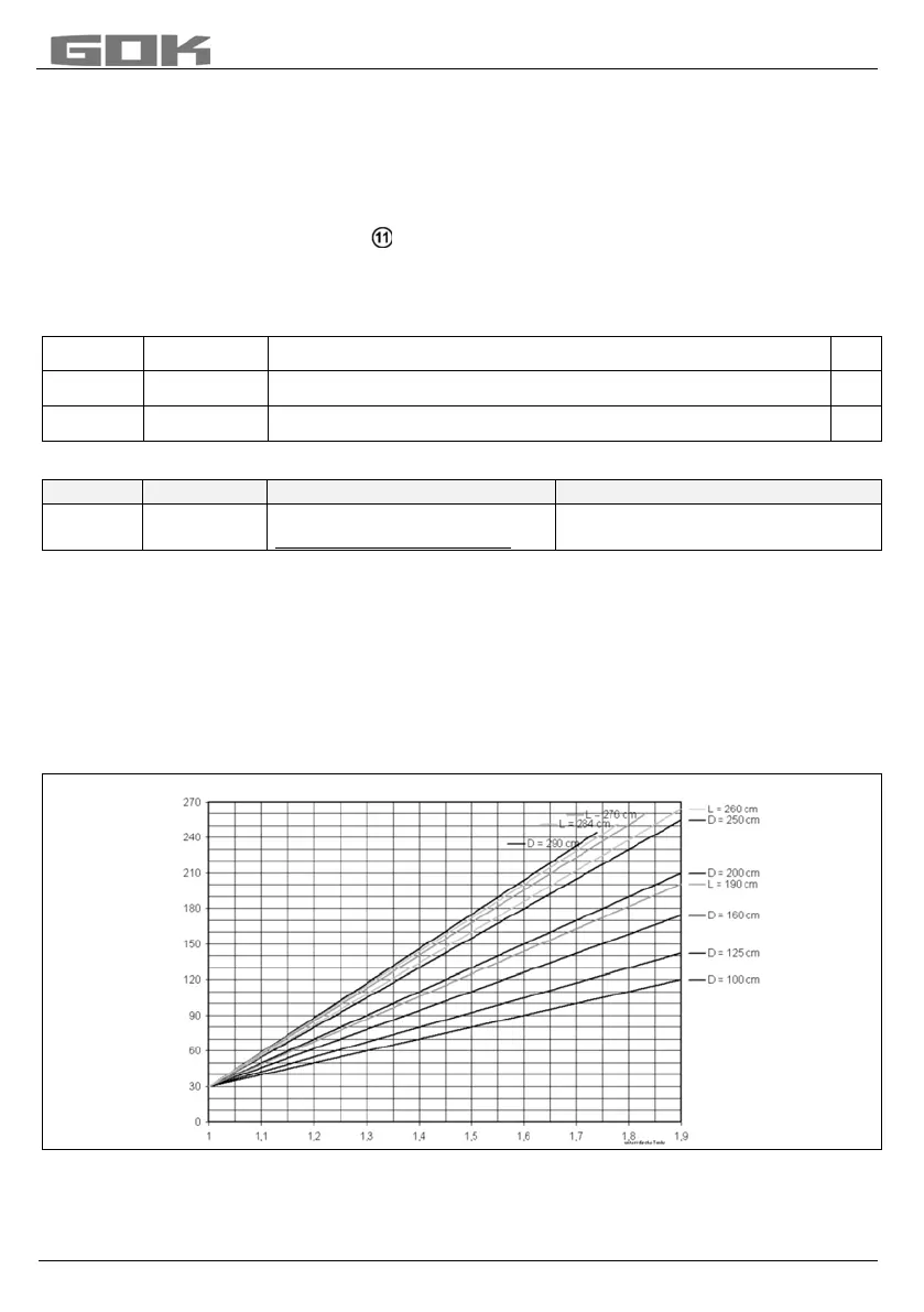
• For underground tanks diagram 3 can be used to determine the minimum installation
dimension a
min
in relation to the density of the storage medium with the parameter tank
diameter D or tank height L.
Assumed as: p
s,2
= 550mbar, w = 0, p
o,1
= 0
• As opposed to calculating the installation dimension a according to EN 13160-3, when the
installation dimension a is calculated according to TRbF 501 and VdTÜV
fact sheet 904, the bottom of the LDL tank is used as the reference line.
Min. installation dimension a
min
for underground tanks acc. to DIN 6608-2, DIN 6619-2
Diagramm 3:
Density of the storage medium in [kg/l]
Minimum installation dimension a
min
[cm]


 To Next Page
 Loading...
