Leak detector type LAG 2000 A
20 / 28 part no. 15 071 53 e
Connect the sensor cable, see Figure 6: Terminal "C"
Insert sensor cable through nipple "A6" on the display unit
Attach the sensor cable to 4 and 5 according to the terminal block designation.
The polarity is unimportant.
If no additional alarm is to be connected to the relay output, screw the front on again with
• To extend the cable, use a connection box or a GOK cable connection fitting (accessory
GOK Art. No. 15 379 00). The cable connection fitting is also included in the GOK assembly
set for the leak detector, GOK Art. No. 15 072 99.
• Use to extend cables with a blue outer sheath or marked with a blue flag for intrinsically
safe circuits.
Install the cable connection fitting IP 54 at the top beside the LDL tank
Connect the sensor cable to the cable connection fitting
Connect the extension sensor cable to the cable connection fitting
Fix the extension sensor cable to the wall
See Figure 6 to connect the extension sensor cable: Terminal „C“
nsert the extension sensor cable through nipple „A6“ on the display unit
Attach the extension sensor cable to 4 and 5 according to the terminal block designation.
The polarity is unimportant.
If no additional alarm is to be connected to the relay output, replace the front with 4
Table 8: Technical data for sensor cable
Sensor cable of the sensor unit
max. 25V - AC
Permissible extension sensor cable
Wet room – NYM
Soil - NYY or similar
Maximum length of extension sensor cable
maximum 100m – with cross section 1.5mm
2
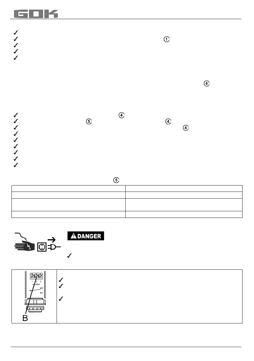
Connection relay output for additional alarm
Electrical potential!
Electric shock risk.
Switch off the power supply and make sure that it cannot be
switched on again inadvertently.
See Figure 8 to connect the cable of the external alarm: Terminal B Alarm:
Insert the cable through the nipple on the display unit.
Connect the cable from the external alarm to 1, 2 or 3 according to the
terminal block designation.
Attach the front with 4 screws.


 To Next Page
 Loading...
