GL102B USER’S GUIDE GOLANDERUSA.COM
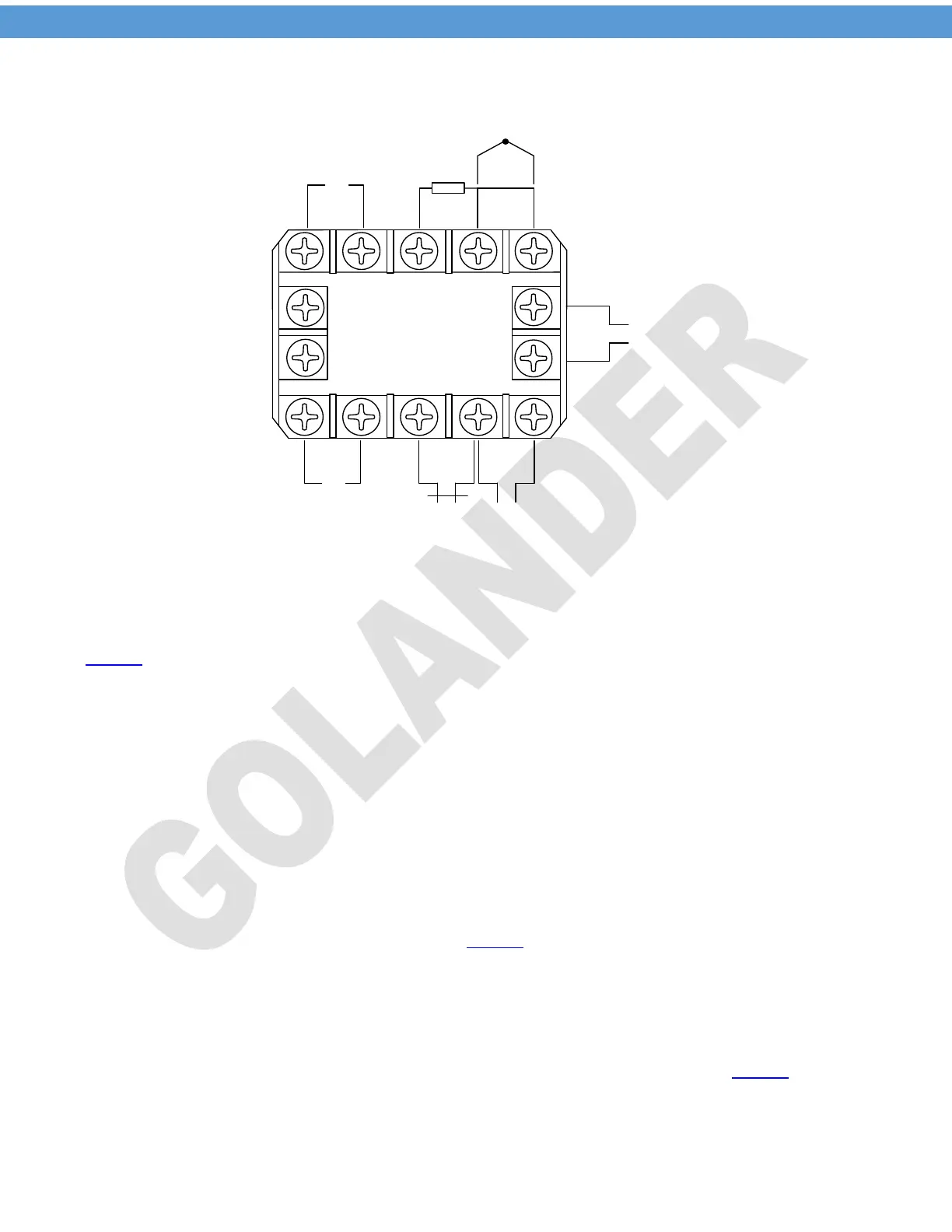
4 Back terminals
8 9 10
1 2
3
4 5
7
6
-
+
SSR
-
+
J1 Relay
9-30V DC
Thermocouple
RTD
11
12
13
14
J2 Relay
+ -
Figure 1 Back Terminals Wiring Diagram
4.1 Sensor connection
The default setting for the input type is for K type thermocouple, for different probe type, the parameter Inty
in Table 1.
For thermocouple, connect the positive wire to terminal 9 and the negative wire to terminal 10. For K type
thermocouple, if the wires are red and yellow, the yellow wire is positive. If they are red and other color
(blue, white, green….), the red is positive. If the polarity is reversed, when the temperature goes higher, the
readout will decrease.
For three-wire PT100 probe, if the wire color code is red, red and white (to IEC60751), connect the two red
wires to terminals 9 and 10 respectively, and connect the white wire to terminal 8. For two-wire PT100
probe, connect one wire to terminal 8 and connect the other wire to terminal 9, and short the terminals 9
and 10. The parameter Inty need to be changed to P10.0 (for 0.1 degree display resolution) or P100 (for 1
degree display resolution).
4.2 SSR connection
When the main control output is set to SSR (Outy in Table 1 is set to 2 or 3), the SSR output is enabled.
The terminal 6 should be connected to the positive pole of the DC control side of the SSR, the terminal 7
should go to the negative pole of the SSR. When there is no SSR connected to the terminals 6 and 7, there
should be around 8V DC between them when the OUT indicator is on.
4.3 J1, J2 relay connection
J2 relay can be set to PID or on/off control output, or set as an alarm relay (see Outy in Table 1). J1 is for
alarm only. Please note the relays are just a switch, there is no power on them. The power need to be
provided to the load connected to the relays.
2
 Loading...