GL102B USER’S GUIDE GOLANDERUSA.COM
4.4 Power to the controller
The controller can be powered by 9-30V DC. Terminal 1 is for positive, terminal 2 is for negative. The
ground power line is not necessary.
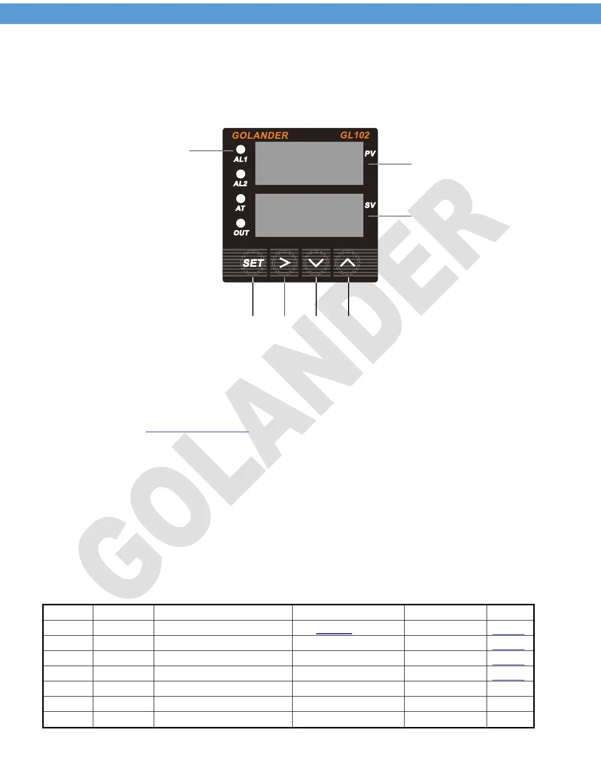
5 Front Panel
Figure 2 Front Panel
1 – Indicators
AL1: relay J1 output indicator. On when J1 relay closed
AL2: relay J2 output indicator. On when J2 relay closed
AT: Auto tune indicator. Flashing during auto tune. On when
in Manual Control Mode
OUT: SSR control output indicator.
2 – Up key, select next parameter or increase value
3 – Down key, select previous parameter or decrease value
4 – Shift Key, Shift the digit when changing the setting, or press and hold
the key to start auto tune
5 – SET key, parameter set/confirm
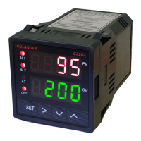
6 – PV, measured value display
7 – SV, target temperature display
6 Initial function parameters (input passcode 0089 after pressing the SET key)
Table 1
INTY
OUTY
HY
PSB
Display temperature offset
RD
CORF
END
3