GL102B USER’S GUIDE GOLANDERUSA.COM
The filter is to increase the measured temperature display stability, but will delay the response. When Filt is
set to 0, the filter is disabled. 1, 2 and 3 are weak, medium and strong, respectively.
8 Auto tune
For PID control mode, if the control with default P, I and d parameters settings are not able to hold the
target temperature, the built-in auto tune function can find the right PID parameters for the system. When on
heating mode, it will heat up the system to the target temperature then let the system cool down. It will
repeat this process for about 3 times, then the controller will calculate the parameters automatically.
To activate the auto tune function, press and hold the > key until the “AT” indicator starts to blink. When
auto tune process finished, the “AT” indicator will stop blinking. The new values for parameters P, I and d
are calculated by the controller.
To stop the auto-tuning, press and hold > key for 3 seconds, until “AT” indicator stops blinking. The PID
parameters values will not change.
Please note:
• Auto tune from time to time, there will be a significant temperature overshoot, please lower SV value
to prevent accident.
• The sensor, load (heater…) need to be connected properly, otherwise, the auto tune will not
complete.
• The time for the auto tune depends on the system response time, would be from a few minutes to
hours.
• Only need to run auto tune one time.
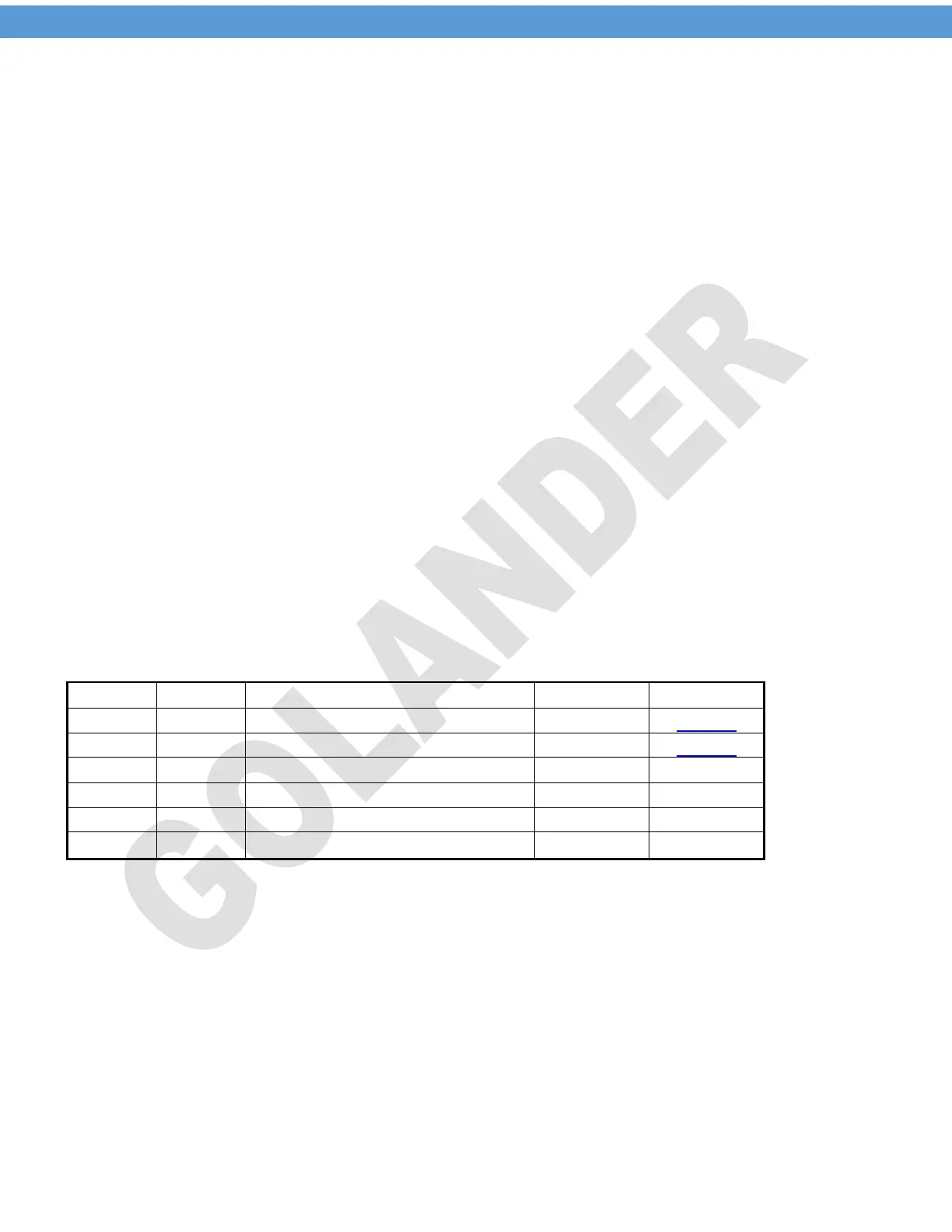
9 SV and alarm parameters (input passcode 0001 after pressing the SET key)
Table 4.
SV
Target temperature (Set Value)
AH1
Alarm (J1 relay) on temperature
AL1
Alarm (J1 relay) off temperature
AH2
Alarm (J1 relay) on temperature
AL2
Alarm (J1 relay) off temperature
END
Note 11. The SV value can be set by accessing the 0001 menu. Or, when in normal operation mode, use
the UP or DOWN key to change the SV directly.
Note 12. When the J1 (J2) relays are set as alarm, the relay will be controlled by the two parameters AH1
(AH2) and AL1 (AL2). The alarm can be set as high alarm or low alarm.
For high alarm, set AH1 (AH2) > AL1 (AL2). When the temperature increase to AH1 (AH2), the J1 (J2)
relay will be closed (alarm on), when the temperature drops down to AL1 (AL2), the J1 (J2) relay will be
open (alarm off).
For low alarm, set AH1 (AH2) < AL1 (AL2). When the temperature decrease to AH1 (AH2), the J1 (J2)
relay will be closed (alarm on), when the temperature increases to AL1 (AL2), the J1 (J2) relay will be open
(alarm off).
7
 Loading...