GL102B USER’S GUIDE GOLANDERUSA.COM
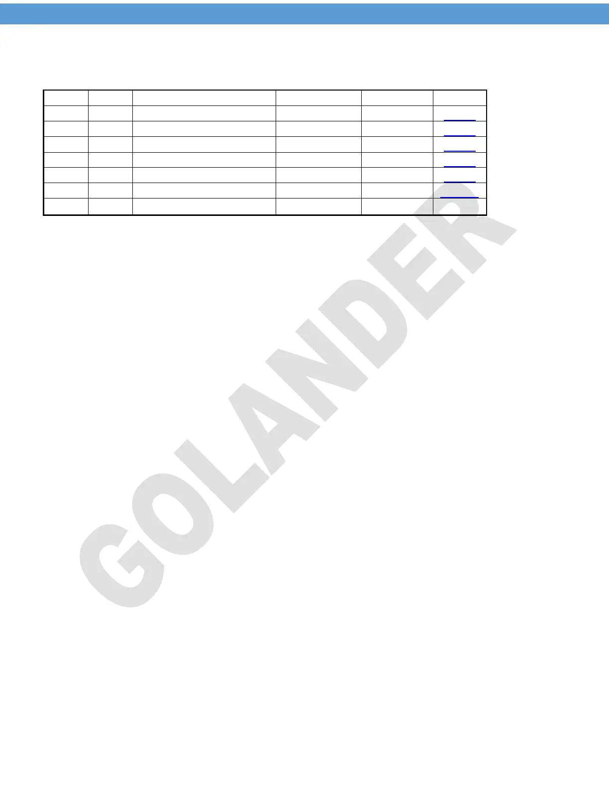
7 PID parameters (input passcode 0036 after pressing the SET key)
Table 3
P
I
D
SOUF
Overshoot suppression factor
OT
FILT
END
Note 5. P – Proportional band
The proportional term produces an output value that is proportional to the current error value. A high
proportional gain results in a large change in the output for a given change in the error. If the proportional
gain is too high, the system can become unstable. In contrast, a small gain results in a small output
response to a large input error, and a less responsive or less sensitive controller. If the proportional gain is
too low, the control action may be too small when responding to system disturbances. In a real system,
proportional-only control will leave an offset error in the final steady-state condition. Integral action is
required to eliminate this error.
Note 6. I – Integral time
The contribution from the integral term is proportional to both the magnitude of the error and the duration of
the error. The integral in a PID controller is the sum of the instantaneous error over time and gives the
accumulated offset that should have been corrected previously. The accumulated error is then multiplied by
the integral gain and added to the controller output. The integral term accelerates the movement of the
process towards set point and eliminates the residual steady-state error that occurs with a pure proportional
controller. However, since the integral term responds to accumulated errors from the past, it can cause the
present value to overshoot the set point value.
Note 7. d – Derivation time
The derivative of the process error is calculated by determining the slope of the error over time and
multiplying this rate of change by the derivative gain. The magnitude of the contribution of the derivative
term to the overall control action is termed the derivative gain. Derivative action predicts system behavior
and thus improves settling time and stability of the system. An ideal derivative is not causal, so that
implementations of PID controllers include an additional low pass filtering for the derivative term, to limit the
high frequency gain and noise. Normally d is set to 25% of the I value.
Note 8. SouF – Overshoot suppression factor
Overshooting and undershooting are restricted by the SouF and increase of the parameter can suppress
the overshooting
Note 9. Proportional cycle
It’s the cycle time to switch the output on/off. Within the cycle t time, the output will turn on and off once. For
SSR, in general the cycle time is set to 2 seconds. For mechanical relays, set the cycle time to a higher
value to save the life time of the relay.
Note 10. Filt – digital filter factor
6
 Loading...