GL102B USER’S GUIDE GOLANDERUSA.COM
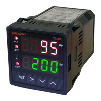
Table 2
T
Internal
resistance
100Kohms
R
J
-200~1200°C; -320~2200 °F
Wre
B
S
K
-200~1300 °C; -320~2400 °F
E
-200~900 °C; -320~1650 °F
P10.0
PT100 RTD, 0.1° resolution
-99.9~600.0 °C; -99.9~999.9 °F
current
output
P100
-200~600 °C; -320~1100 °F
Cu50
-50.0~150.0 °C; -60~300 °F
Note 2. Outy - Control output type
0: Set J1, J2 relays as alarm output, SSR output disabled.
1: Set J1 relay as alarm output, J2 relay as PID control output, SSR output disabled. SV is the control
temperature.
2: Set J1, J2 relays as alarm output, set SSR as PID control output. SV is the control temperature.
3: Set J1, J2 relays as alarm output, set SSR as on/off control output. SV is the control temperature.
4. Set J1 relay as alarm output, set J2 relay as on/off control output. SSR output disabled.
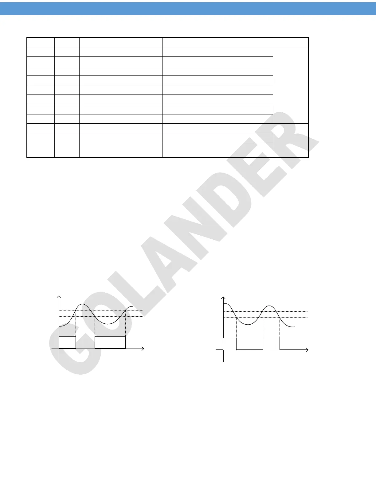
Note 3. Hy - Hysteresis Band
The parameter Hy is only for on/off control. For heating control mode, when the measured temperature PV
reaches the target temperature SV, the control output will be off; when PV drops down to SV-Hy, the control
output will be on again. For cooling control mode, when PV drops down to SV, the control output will be off,
when PV increases to SV+Hy, the control output will be on again.
Outpu t
on
SV
SV-Hy
PV
Outpu t
on
SV+Hy
PV
SV
Outpu t
on
Outpu t
on
Heating control
Cooling control
Figure 4. on/off control
Note 4. Psb - Display temperature offset
This feature allows the input value to be changed to agree with an external reference or to compensate for
sensor error. For example, if the measured temperature of the controller is 100 degrees, but the reference
temperature is 98 degrees. By setting the Psb= -2, the PV display of the controller would change to be 98.
To set the negative value for Psb, use the shift key to move the focus digit to the first digit from the left, then
use the down key to change the digit to show the negative symbol.
5
 Loading...