7
Wall
Side
View
Corner
To p
View
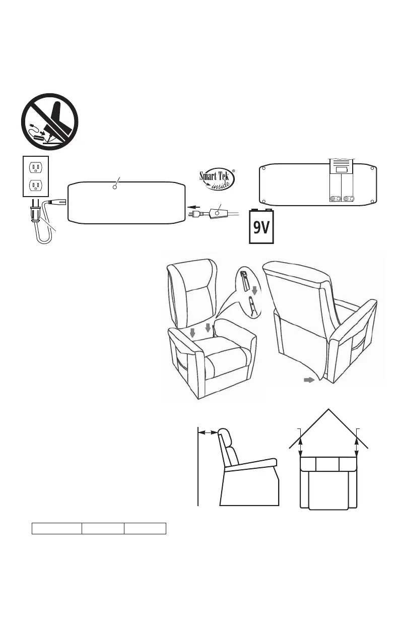
17"
17" 17"
Distance Required From Wall
When Reclined
Model No. Wall Corner
6.
Adjust the leg levelers on the bottom of the chair if necessary to level the chair.
Some high pile carpets can obstruct the footrest operation by rubbing against
it. Adjust the levelers to a height above the pile.
7.
Installation Of Your Power Lift Chair
Model 118
1.
Remove the transformer and hand control from under the chair and place
two 9 volt batteries in transformer as shown. Place transformer on
the fl oor behind the chair.
2. Plug the transformer into a 115-120V 60Hz A.C. outlet and connect
the power cable from the chair into the transformer as shown. Power
cable is located under the chair attached to the motor with white zip
tie. Remove zip tie, extend the cable under and out behind the chair.
PR-118
17 in. 17 in.
L.E.D. light
L.E.D. light
From motor
To outlet
115-120V A.C.
DC Power
Bottom view of
Transformer
Transformer
Plug
Install two 9 volt batteries
in transformer for battery
backup (See page 11)
(batteries not included)
P
A
T
E
N
T
E
D
3.
Plug the hand control into the
lock located at the back of the
seat and lay it on top of the seat
see page 8 hand control
routing.
4.
5.
Align the back brackets and the
seat brackets, then push on the
seat back until they are locked
into place.
Attach the bottom of the
outside back to the Velcro on
the arm cross rail.
Place the chair in the desired
position in the room, keeping it
17" from the wall. If placing the
chair into a corner, keep it 17"
from the wall as shown. See
distance chart below for your
model.