2
SAFETY PRECAUTIONS
- Telephone with simple installation (2 wire BUS ).without polarity
- Up to 4 telephones/monitors per apartment (master, slave 1, slave 2 and slave 3).
- Up to 32 apartments/telephones per installation.
- Completely private conversation.
- Call volume control (maximum, medium and mute).
- Input for calls from the apartment's door.
- Call repeater output.
- Different ring tones indicate the origin of the call: door panel, intercom and apartment door.
- Lock release push button1 activation .
- 2 / activation light function "stairs light" (it requires of SAR-GB2 & SAR-12/24Intercom/lock release
modules) .push button Note:The light function only with T562 Telephones with V.03or later.
- .Push button for setting ring tones (inside the telephone)
- Dip switches for setting the telephone address (call code), master/slave, end of line and activating the
“doctor mode” (inside the telephone).
- Install or modify the equipment without the power connected.
- The installation and handling of these equipments must be performed by authorised personnel.
- entire installation must beThe at least away from any other40 cm installation.
- Do not overtighten the screws on the terminal block.
- and place without risk of drop or water projectionsInstall the telephone in a dry protected .
-Avoid to place it near to heating sources, in dusty locations or smoky enviroments.
- Before connecting the system to the mains, check the connections between the door panel,
power supply and telephones.
- Do a the enclosed informationlways follow .
CHARACTERISTICS
SYSTEM OPERATION
- To make a call the visitor should press the button corresponding to the desired apartment; an
audible tone indicates that the call is being made and the will turn on. If thedoor panel LED
vocal synthesis is the “call ” willenabled message is in progress be heard confirming the call is in
progress. At this moment the apartment's telephone(s) receive(s) the call. During the call the
visitor can correct his call by pressing a push button corresponding to a different apartment, in
which case the original call is cancelled.
- The call lasts for 40 seconds. If the call is not answered within 40 seconds, the LED will turn off
and the channel will be freed.
- To establish communication, lift the handset of any telephone in the apartment. The door panel LED
will turn on. If the vocal synthesis is enabled the message "you can speak now" will be heard confiming
the communication is activated
- The communication will last for one and a half minutes or until the handset is replaced. When
communication has finished the and LEDs will turn off and the channel will be freed. If the
vocal synthesis is the “c ” willenabled message ommunication is finished be heard in the door
panel confirming the communication has finished.
- To open the door, press the push button (to open the second door, if there is one, press the
....... push button) during the call or communication processes: one press will activate the lock
release for five seconds and the LED will also turn on during this time. If the vocaldoor panel
synthesis is the “door open” will be on the door panel.enabled message is heard
- The descriptions of the function push buttons are found on page 3.
*
( )
*
( )
For further information see the “T562 GB2 (code 50121599)” user manual.
https://doc.golmar.es/search/manual/50121599
3
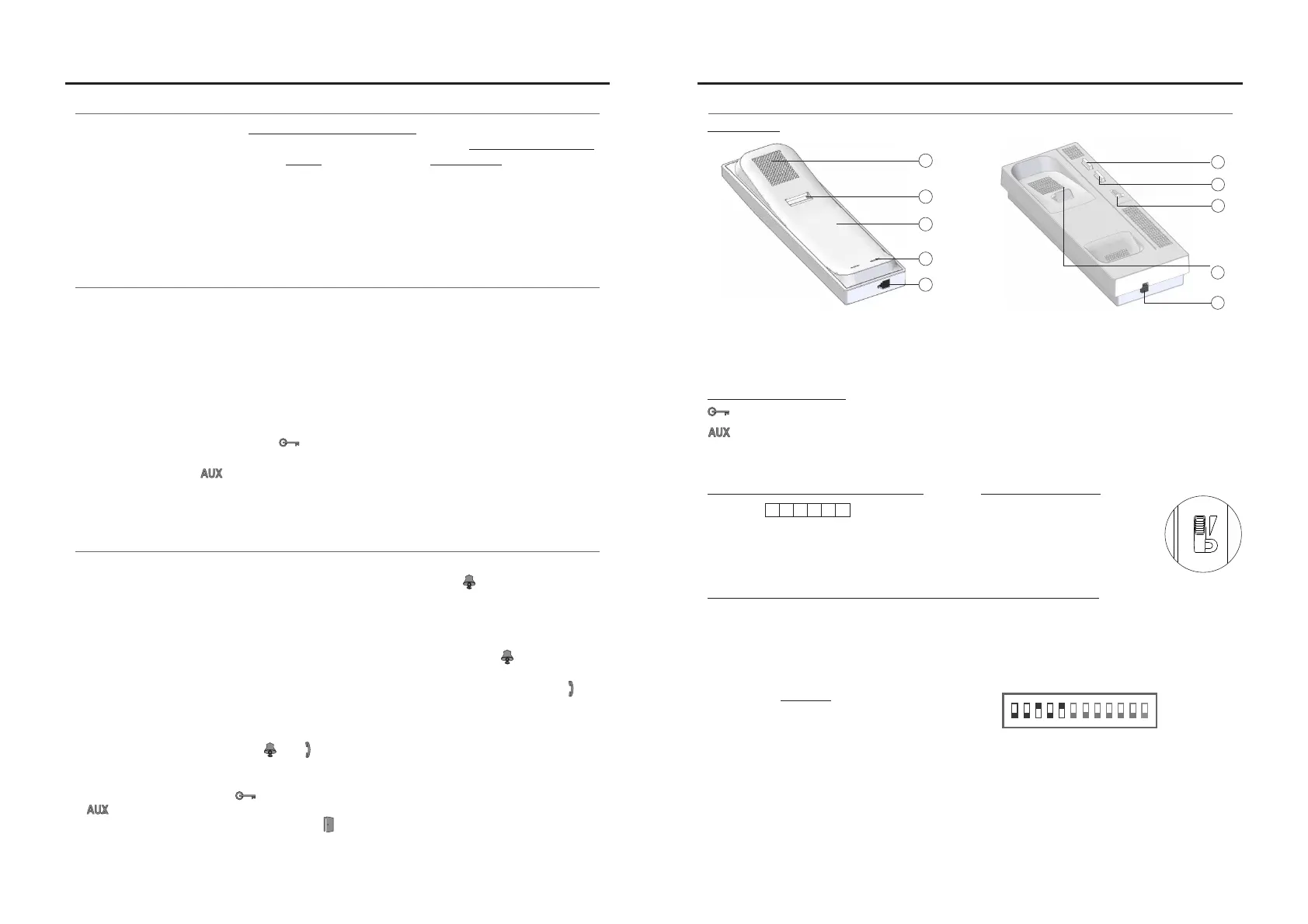
TELEPHONE DESCRIPTION
*
( )
Activates lock release 1 during the call reception and communication processes.
Activates lock release 2 during the call reception and communication processes.
During standby:
- .With the handset lifted it enables intercom functionality
- With the handset on the craddle it enables light function (it requires SAR-GB2 & SAR-12/24 modules).
Function push buttons:
Call volume control:
*
( )
For further information see the ode user manual“T562 GB2 (c . 50121599)” .
https://doc.golmar.es/search/manual/50121599
T562 G 2B
TELEPHONE T562 G 2B TELEPHONE
a
d
c
e
b
g
e
a.
b.
c.
d.
e.
Handset.
Speaker grille.
Microphone hole.
Subjection hole.
Telephone cord connectors.
f
h
i
Lock release push button.
Hook switch.
Auxiliary function push button.
Volume control.
f.
g.
h.
i.
The telephone has a call
volume control which can
be set to maximum, medium
or mute.
Description of dip switch and setting of telephone address (code):
*
( )
1 2 3
ON
E : 0 + 0+4+0+16 = 20xample
Switch number: 1 2 3 4 5
1 2 4 8 16Value ON:
Value chart
4 5 6
Dip1 Dip5:to Set the telephone address (addresses 0 to 31).
Dip6 Dip7:and OFF.Leave
Switches set to OFF have a value of zero.
The values of the switches set to ON are shown in the enclosed chart.
The telephone code will be the sum of the values of the switches set to ON.
Dip8 Dip9:and Set the telephone as master/slave. Dip8 and Dip9 OFF, master; Dip8 ON and Dip9 OFF, slave 1;
Dip8 OFF and Dip9 ON, slave 2; Dip8 and Dip9 ON, slave 3.
Dip10: OFF.Leave
Dip11: Sets the end of line It should always be set to OFF in installations with only telephones. In installations with.
monitors and telephones in the same apartment, set to ON for the telephones at which the BUS cable ends, and
set to OFF for intermediate telephones.
Dip12: " "Setting this to OFF makes the volume control's OFF position function as mute .
Setting this to ON makes the volume control's OFF position function as doctor mode ." "
Description of connection terminals:
BUS connection.
Door bell push button connection.
Call repeater connection, (SAR-12/24).
(12V c/50mA m xim ).d a um
L1 L2, :
HZ ,
:
SA , :
SAL1 L2
_
HZ
_
_
_
7 8 9 10 11 12
Descrip :tion
 Loading...