EasyManua.ls Logo

Goodman CONDENSING AC UNIT User Manual

Goodman CONDENSING AC UNIT
8 pages
To Next Page IconTo Next Page
Page #1 background imageLoading...
Page #1 background image
Important Safety Instructions
The following symbols and labels are used throughout this
manual to indicate immediate or potential safety hazards. It is
the owner’s and installer’s responsibility to read and comply
with all safety information and instructions accompanying these
symbols. Failure to heed safety information increases the risk
of personal injury, property damage, and/or product damage.
HIGH VOLTAGE!
Disconnect ALL power before servicing.
Multiple power sources may be present.
Failure to do so may cause property damage,
personal injury or death.
WARNING
ONLY individuals meeting the requirements of an
“Entry Level Technician”, at a minimum, as specified
by the Air Conditioning, Heating and Refrigeration
Institute (AHRI) may use this information. Attempting
to install or repair this unit without such background
may result in product damage, personal injury,
or death.
Shipping Inspection
Always keep the unit upright; laying the unit on its side or top
may cause equipment damage. Shipping damage, and subse-
quent investigation is the responsibility of the carrier. Verify
the model number, specifications, electrical characteristics,
and accessories are correct prior to installation. The distribu-
tor or manufacturer will not accept claims from dealers for trans-
portation damage or installation of incorrectly shipped units.
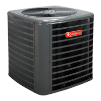
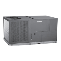
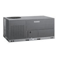
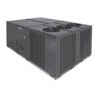
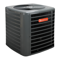
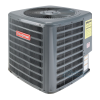
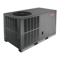
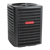
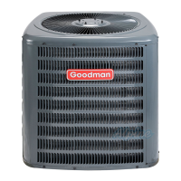
CONDENSING AC UNIT
3-PHASE 7.5 & 10 TON AIR CONDITIONER
INSTALLATION & SERVICE REFERENCE
© 2010 Goodman Manufacturing Company, L.P.
5151 San Felipe, Suite 500, Houston, TX 77056
www.goodmanmfg.com -or- www.amana-hac.com
P/N: IO-404 Date: November 2010
Codes & Regulations
This product is designed and manufactured to comply with
national codes. Installation in accordance with such codes and/
or prevailing local codes/regulations is the responsibility of the
installer. The manufacturer assumes no responsibility for equip-
ment installed in violation of any codes or regulations.
The United States Environmental Protection Agency (EPA)
has issued various regulations regarding the introduc-
tion and disposal of refrigerants. Failure to follow these
regulations may harm the environment and can lead to
the imposition of substantial fines. Should you have any
questions please contact the local office of the EPA.
If replacing a condensing unit or air handler, the system must
be manufacturer approved and Air Conditioning, Heating and
Refrigeration Institute (AHRI) matched.
Refer to the unit Specification Sheet for the recommended in-
door model selection. NOTE: This unit must be used with a
purchased single stage room thermostat with 24 VAC control
circuitry.
Do not operate the unit in a structure that is not complete
(either as part of new construction or renovation). Such opera-
tion will void the warranty.
Installation Clearances
This unit is designed for outdoor installations only. Special
consideration must be given to location of the condensing unit(s)
in regard to structures, obstructions, other units, and any/all
other factors that may interfere with air circulation. Where
possible, the top of the unit should be completely unobstructed;
however, if vertical conditions require placement beneath an
obstruction there should be a minimum of 60 inches be-
tween the top of the unit and the obstruction(s). The speci-
fied dimensions meet requirements for air circulation only.
Consult all appropriate regulatory codes prior to determining
final clearances.
NOTICE
THIS UNIT IS SHIPPED WITH A NITROGEN/HELIUM HOLDING CHARGE ONLY. UNIT
MUST BE EVACUATED AND CHARGED PER INSTALLATION INSTRUCTIONS WITH
REFRIGERANT LISTED ON SERIAL RATING PLATE.
UNITS SHIPPED WITH A HOLDING CHARGE ARE INTENDED FOR COMPONENT
REPLACEMENT ONLY ON EXISTING SYSTEMS, AND NOT INTENDED FOR USE IN
NEW SYSTEMS OR NEWLY CONSTRUCTED HOMES.
NOTICE
NOTICE
UNITS MUST ONLY BE USED AS REPLACEMENT COMPONENTS FOR PRE-2010
INSTALLED SYSTEMS.

Questions and Answers:

Goodman CONDENSING AC UNIT Specifications

General IconGeneral
BrandGoodman
ModelCONDENSING AC UNIT
CategoryAir Conditioner
LanguageEnglish

Summary

Important Safety Instructions

High Voltage Warning

Disconnect all power before servicing. Multiple sources may be present. Failure to do so may cause injury or death.

Technician Qualification

Only individuals meeting "Entry Level Technician" requirements may use this info. Improper use may cause damage, injury or death.

Shipping Inspection

Keep unit upright. Verify model, specs, electricals. Carrier responsible for shipping damage.

Codes & Regulations

Installation Compliance

Installer responsible for complying with national, local codes. Manufacturer not liable for violations.

Refrigerant Regulations

Follow EPA regulations for refrigerant handling to avoid harm and fines. Contact EPA for questions.

System Matching

System must be manufacturer approved and AHRI matched. Use specified indoor model and 24 VAC thermostat.

Installation Clearances

Designed for outdoor use. Ensure adequate air circulation. Minimum 60" clearance to obstructions above.

Location Considerations

Obstruction Angles

Angle side adjacent to structure towards it, maintain clearance away. Corner installations discouraged.

Foundation Requirements

Unit must be on a solid, level foundation. Slab should be 6" wider than unit, not integral to building foundation for sound.

Interconnecting Tubing

Site should be within 50' below or 70' above evaporator. Minimize tubing length and bends for performance.

Rooftop Installations

Structural Support

Ensure roof structure supports unit weight and maintains weather-tight integrity.

Vibration Isolation

Consider sound/vibration transmission. Use vibration absorbing pads or springs between unit legs and roof assembly.

Rigging

Lifting Precautions

Secure all panels before lifting. Use spreader bars, protective material, and a central suspension point.

Safe Refrigerant Handling

Breathing Hazard

Refrigerants displace oxygen. Never purge in enclosed spaces. Ventilate if indoor leak suspected. Avoid contact with cold liquid.

Cylinder Safety

Never apply flame/steam to cylinders. Heat in warm water if needed. Do not overfill or mix refrigerants. Store in cool, dry place.

Refrigerant Cylinder Safety

Cylinder Usage

Use returnable cylinders, free of damage. Ensure hydrostatic test date is not over 5 years and pressure rating is adequate.

Refrigerant Lines

System Components

Equip evaporator with TXV and liquid line with solenoid. Install solenoid near evaporator to prevent migration.

Tubing Installation

Use refrigerant grade copper tubing. Cut square, clean, and plug ends. Avoid contact with building elements; use vibration absorbing material.

Insulation Requirements

Insulate suction line to prevent condensation. Use 3/8" minimum wall thickness; 1/2" may be needed in humid areas.

Oil Return

Drain residual oil. Pitch horizontal suction lines 1/2" per 10' toward condensing unit for oil return.

Filter Drier and Sight Glass

Field-install sight glass/moisture indicator on liquid line near service valve.

Burying Refrigerant Lines

Insulate lines separately, enclose in waterproof material, and seal ends. Protect lines passing under concrete slabs.

Refrigerant Line Connections

Brazing Procedures

Remove holding charge. Wrap valves with wet rag or heat trap. Use 2% silver alloy, no flux. Sweep with nitrogen.

Post-Brazing Steps

Quench joints with water. Ensure filter drier paint is intact; repaint if burned/chipped. Avoid kinking/denting lines.

Leak Testing

Use dry nitrogen and soapy water. Never use oxygen, high-pressure air, or flammable gases. Ensure pressure regulator and relief valve.

System Evacuation

Evacuation Process

Close valves. Connect vacuum pump (250 micron). Evacuate to 250 microns or less using both valves. Hold vacuum.

Electrical Connections

High Voltage Warning

Disconnect power before servicing. Multiple sources may be present. Failure to do so may cause injury, death or damage.

Wiring Standards

Wiring must conform to NEC/CEC and local codes. Use copper conductors. Undersized wires may cause damage or fire.

Unit Power Requirements

Unit is three-phase. Do not operate on single-phase. Supply voltage must agree with unit rating plate.

Voltage Unbalance Calculation

Supply voltage can be unbalanced within 2% phase-to-phase. Formula provided to determine percentage of unbalance.

Overcurrent Protection

Approved Devices

Approved devices include time delay fuses and HACR type circuit breakers for motor-compressor starting.

Wiring Conduit

Run line voltage wiring in conduit from disconnect box to unit. Use appropriate size conduit and flexible conduit if permitted.

Three Phase Compressor Rotation

Rotation Verification

Verify rotation by checking suction pressure drop and discharge pressure rise. Reverse if necessary.

High Voltage Connections

Low Voltage Connections

Thermostat Wiring

Requires two-conductor low voltage from thermostat. Use 18 AWG minimum. Connections made in control box using solderless connectors.

System Start Up

Compressor Operation

Never operate compressor with suction valve closed. This can cause damage and void warranty.

Charge Verification

Refrigerant Pressure Warning

Do not overcharge or operate in vacuum/negative pressure. Failure to follow procedures may cause injury or death.

Refrigerant Certification

Use AHRI certified refrigerant. Used refrigerant may damage compressor and is not covered under warranty.

EPA Regulations

Violation of EPA regulations may result in fines or other penalties.

Compressor Valve Warning

Operating compressor with suction valve closed may cause serious compressor damage.

Final Charge Adjustment

Pre-Adjustment Steps

Outdoor temp must be 60°F+. Set thermostat to COOL, fan to AUTO, temp control below room temp.

Expansion Valve System

Subcooling and Superheat Check

Check subcooling (11±2°F) and superheat (9±1°F). Adjust TXV or charge as needed based on readings.

Valve Core Torque

Torque valve bonnets 1/6 turn past finger tight for an effective seal. Tighten Schrader ports if necessary.

Troubleshooting

Initial Checks

First step is to check clean coils, filters, and proper airflow. Indoor airflow should be 375-425 CFM per ton.

Wiring Diagram

High Voltage Warning

Disconnect all power before servicing or installing. Multiple power sources may be present. Failure to do so may cause injury or death.

Related product manuals