EasyManua.ls Logo

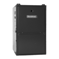
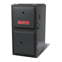
Goodman GC9S80 User Manual

Goodman GC9S80
55 pages
To Next Page IconTo Next Page
Page #1 background imageLoading...
Page #1 background image
Service and Troubleshooting


Copyright © 2021 Goodman Manufacturing Company, L.P.
RS6621008
July 2021
TABLE OF CONTENTS
IMPORTANT INFORMATION ............................................ 2
PRODUCT IDENTIFICATION ........................................... 4
SYSTEM OPERATION ...................................................... 5
SCHEDULED MAINTENANCE ....................................... 25
SERVICING ..................................................................... 29
CHECKING VOLTAGE .............................................. 30
CHECKING WIRING .................................................. 30
CHECKING THERMOSTAT, WIRING ....................... 30
CHECKING TRANSFORMER AND CONTROL
CIRCUIT ...................................................................... 31
CHECKING AIR CIRCULATOR BLOWER MOTOR 31
CHECKING DUCT STATIC ........................................ 32
CHECKING TEMPERATURE RISE .......................... 32
CHECKING PRIMARY LIMIT CONTROL ................. 33
CHECKING AUXILIARY LIMIT CONTROL ............... 33
CHECKING FLAME ROLLOUT CONTROL ............. 34
INDUCED DRAFT BLOWER MOTOR ...................... 35
CHECKING GAS VALVE (REDUNDANT) ................ 35
CHECKING MAIN BURNERS ................................... 35
CHECKING ORIFICES .............................................. 35
CHECKING GAS PRESSURE .................................. 36
CHECKING HOT SURFACE IGNITER ..................... 38
CHECKING FOR FLASHBACK ................................. 38
CHECKING PRESSURE SWITCH............................ 38
HIGH ALTITUDE APPLICATION ............................... 39
CHECKING FOR DELAYED IGNITION .................... 39
CHECKING INTEGRATED IGNITION CONTROL
BOARDS ..................................................................... 40
CHECKING FLAME SENSOR ................................... 40
AIRFLOW TABLES ........................................................ 42
1 STAGE STATUS CODES ........................................... 50
1 STAGE TROUBLESHOOTING CODES.................... 52
WIRING DIAGRAMS ....................................................... 54
Pride and workmanship go into every product to provide
our customers with quality products. It is possible, however,
that during its lifetime a product may require service.

technician who is familiar with the safety procedures
required in the repair and who is equipped with the proper
tools, parts, testing instruments and the appropriate service
manual. 







-
-










Questions and Answers:

Goodman GC9S80 Specifications

General IconGeneral
ModelGC9S80
AFUE Rating80%
Heat Exchanger MaterialAluminized Steel
Fuel TypeNatural Gas
StagesSingle Stage
CabinetHeavy Gauge Steel
Vent Size4 inches

Summary

Important Information

Safety Warnings

Contains critical warnings regarding electrical shock, flammable materials, and high voltage hazards.

System Operation

Normal Operation Sequences

Details startup, heating, cooling, and fan-only sequences, including delays.

Furnace Startup Procedure

Step-by-step guide for safely starting up the furnace for the first time.

Gas Heat Sequence of Operation

Describes the operational sequence when the furnace calls for heat.

Cooling Mode Sequence of Operation

Details the operational sequence for low stage and second stage cooling.

Furnace Shutdown Procedure

Step-by-step guide for safely shutting down the furnace.

Safety Precautions

General warnings and cautions for installation, adjustment, and operation.

Location Requirements and Considerations

Guidance on selecting an appropriate and safe location for furnace installation.

Combustion and Ventilation Air Requirements

Details requirements for providing adequate air for combustion and ventilation.

Air for Combustion and Ventilation

Covers methods for calculating and providing combustion air requirements.

Indoor Combustion Air

Methods for determining and providing indoor air for combustion.

Outdoor Combustion Air

Methods for calculating and providing outdoor air for combustion.

Combination Indoor and Outdoor Combustion Air

Guidance on using a mix of indoor and outdoor air for combustion.

Category I Venting (Vertical)

Details requirements for Category I venting for 80% furnaces.

Masonry Chimneys

Warnings and considerations for venting through masonry chimneys.

Scheduled Maintenance

Annual Inspection

Annual service checks for furnace components to ensure proper working order and function.

Servicing

Gas Valve Checks

Procedure for checking the gas valve's manual and automatic control functions.

Gas Pressure Measurement and Adjustment

Measuring and adjusting inlet and manifold gas pressures for proper furnace operation.

Integrated Ignition Control Board Checks

Troubleshooting the integrated ignition control for flame sensing and lockout issues.

Flame Sensor Checks

Procedure to check flame sensor signal, continuity, and cleaning.

1 Stage Troubleshooting Codes

Troubleshooting Chart

Lists symptoms, LED status, fault descriptions, and corrective actions for furnace operation.

Troubleshooting Chart Continued

Additional fault descriptions and corrective actions for furnace operation.

Related product manuals