30
SCREEN
(OPTIONAL)
AIR
INTAKE
90°
ELBOWS
12" MIN. ABOVE
HIGHEST ANTICIPATED
SNOW LEVEL
3”-24” BETWEEN PIPES
Combustion Air Intake may also be snorkeled to obtain 12” min
ground clearance.
Alternate Vent Termination Above Anticipated Snow
Level (Dual Pipe)
In a basement installation, the pipes may be run between the joist
spaces. If the pipes must go below the joist and then up into the
last joist space to penetrate the header, two 45° elbows should be
used to reach the header rather than two 90° elbows.
VENT/INTAKE TERMINATIONS FOR I NSTALLATION OF MULTIPLE
DIRECT VENT FURNACES
If more than one direct vent furnace is to be installed vertically
through a common roof top, maintain the same minimum clear-
ances between the exhaust vent and air intake terminations of
adjacent units as with the exhaust vent and air intake terminations
of a single unit.
If more than one direct vent furnace is to be installed horizontally
through a common side wall, maintain the clearances as in the
following figure. Always terminate all exhaust vent outlets at the
same elevation and always terminate all air intakes at the same
elevation.
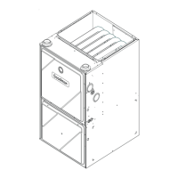
PRODUCT DESIGN
3” MIN
12” MIN TO GRADE OR HIGHEST
ANTICIPATED SNOW LEVEL
12” MIN SEPARATION
3”MIN
24”MAX
OPTIONAL
INTAKE
SCREENS
Termination of Multiple Direct Vent Furnaces
CONCENTRIC VENT T ERMINATION
Refer to the directions provided with the Concentric Vent Kit
(DCVK) for installation specifications.