Do you have a question about the Goodman GMV950453BX Series and is the answer not in the manual?
Describes the furnace's electronic ignition, induced draft blower, and diagnostic control module.
Details requirements for furnace placement, including clearances and floor protection.
Explains the need for high altitude kits due to changes in air density at higher elevations.
Provides data on negative pressure switch trip points for typical sea level operation.
Details pressure switch trip points for furnaces installed at altitudes between 7,001-11,000 ft.
Lists compatible indoor coils for GMV95 and GCV9 furnaces using R22 and R-410A refrigerants.
Recommends specific thermostats for use with GMV95 and GCV9 furnace models.
Outlines requirements for furnace filters, including compliance standards and types.
Specifies filter sizes for side and bottom returns in upflow furnace configurations.
Details filter sizes for counterflow top return configurations based on cabinet width.
Provides heating airflow (CFM) data for various speed taps across GMV95 furnace models.
Lists cooling airflow (CFM) for GMV95 models, covering high, low, and continuous fan speeds.
Provides heating airflow (CFM) data for various speed taps across GCV9 furnace models.
Lists cooling airflow (CFM) for GCV9 models, covering high, low, and continuous fan speeds.
Explains blower speed adjustment switches and ramping profile selection.
Graphical representation of furnace output and temperature rise, including calculation formulas.
Illustrates the wiring connections for the blower assembly of GMV95/GCV9 furnaces.
Presents a general wiring schematic for the integrated ignition control system.
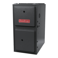
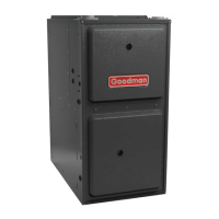
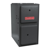
| Model | GMV950453BX |
|---|---|
| Series | GMV95 |
| Type | Gas Furnace |
| Efficiency Rating | 95% AFUE |
| Heating Capacity | 45, 000 BTU/h |
| Blower Motor | Variable Speed |
| Fuel Type | Natural Gas |
| Vent Type | Direct Vent |
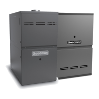
| Configuration | Upflow/Horizontal |
| Stages | Single Stage |
| Motor Type | ECM |
| Gas Valve | Single Stage |
| Ignition | Hot Surface Ignition |
| Heat Exchanger | Stainless Steel |
| Warranty | Lifetime Heat Exchanger, 10-Year Parts |



 Loading...