7
In accordance with the N.E.C. or local codes, install a branch cir-
cuit fused disconnect near the unit. Determine wire sizes and
overcurrent protection from the unit nameplate ampacity and in
accordance with the Minimum Filter Size or the N.E.C. The wiring
should never be sized smaller than is recommended by either of
these two sources.
Fuses smaller than that recommended on the rating plate could
result in unnecessary fuse failure or service calls. The use of
protective devices of larger size than indicated could result in ex-
tensive damage to the equipment. The manufacturer bears no
responsibility for damage caused to equipment as result of the
use of larger than is recommended size protective devices.
All units have undergone a run test prior to packaging for ship-
ment. This equipment has been started at minimum rated voltage
and checked for satisfactory operation. Do not attempt to operate
this unit if the voltage is not within the minimum and maximum
voltages shown on nameplate.
All exterior wiring must be within approved weatherproof conduit.
The unit must be permanently grounded in accordance with local
codes, or in absence of local codes, with N.E.C ANSI/ NFPA NO.
70-1984 or latest edition by using ground lug in the control box.
Fuses or HACR type circuit breakers may be used where codes
permit.
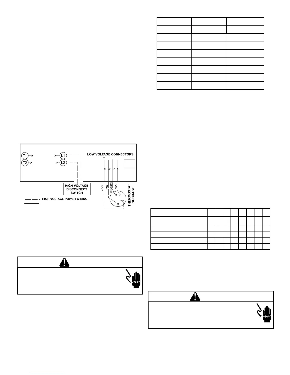
CONTACTOR
R
W
G
G
RW
FOR INTERNAL WIRING SEE WIRING LABEL ATTACHED TO UNIT
24 VOLT CONTROL WIRING
See
*NOTE
*NOTE:
LOW VOLTAGE CONNECTORS do not apply to heat pumps with
electric heat.
IMPORTANT NOTE: Some single phase units are equipped with a
single-pole contactor. Exercise caution when servicing as only one
leg of the power supply is broken with the contractor.
To wire the unit, make the following high and low voltage connec-
tions.
WARNING
HIGH VOLTAGE!
DISCONNECT ALL POWER BEFORE SERVICING OR INSTALLING
THIS UNIT.
MULTIPLE POWER SOURCES MAY BE PRESENT. FAILURE
TO DO SO MAY CAUSE PROPERTY DAMAGE, PERSONAL INJURY OR
DEATH.
HIGH V OLTAGE W IRING
• Single Phase- Two leads should be connected to terminals
L1 & L2 in the electrical control section, using wire sizes
specified in wiring table.
LOW V OLTAGE W IRING
• Heat Pumps- Connect 24V wires from the thermostat to
the corresponding wires in the control box using No. 18
AWG as follows:
GPH15 24 - 36 42 - 60
Terminal Thermostat Thermostat
Red R (24V) R (24V)
Green G (fan) G (fan)
Orange O (rev. valve) O (rev. valve)
White
W1 (heat, 2
nd
) W1 (heat. 2
nd
)*
Brown
W2 (heat, 3
rd
) W2 (heat, 3
rd
)*
Purple Not used Y1 (Low cool)
Yellow Y (cool) Y2 (Hi cool)
Thermostats must be set to energize "G" during cooling.
This is default on most all thermostats.
GPH1542 - GPH1560 have 2-stage cooling and require
2-stage heat/cool with optional
third stage electric heat thermostat.
*Optional field installed heat connections
INTERNAL W IRING
A diagram detailing the internal wiring of this unit is located on the
electrical box cover. If any of the original wire supplied with the
appliance must be replaced, the wire gauge and insulation must
be the same as the original wiring.
Transformer is wired for 230 volts on the 208/230 models. See
wiring diagram for 208 volt wiring.
1. For branch circuit wiring (main power supply to unit
disconnect), the minimum wire size for the length of run
can be determined using the circuit ampacity found on the
unit rating plate and the table below. From the unit
disconnect to unit, the smallest wire size allowable may be
used for the ampacity, as the Disconnect must be in sight
of the unit.
BRANCH CIRCUIT AMPACITY
15 20 25 30 35 40 45 50
SUPPLY WIRE LENGTH -
FEET
200 64443322
150 86644433
100 108866644
50 141210108866
2. Wire size based on 60° C rated wire insulation and 30° C
Ambient Temperature (86° F).
3. For more than 3 conductors in a raceway or cable, see the
N.E.C. for derating the ampacity of each conductor.
STARTUP, ADJUSTMENTS, AND CHECKS
WARNING
HIGH VOLTAGE!
DISCONNECT ALL POWER BEFORE SERVICING OR INSTALLING
THIS UNIT.
MULTIPLE POWER SOURCES MAY BE PRESENT. FAILURE
TO DO SO MAY CAUSE PROPERTY DAMAGE, PERSONAL INJURY OR
DEATH.
 Loading...