This document serves as a technical information manual for MBR/MBE blowers, providing essential details for their function, usage, and maintenance. It is specifically designed for qualified, professionally trained HVAC technicians, as Goodman Manufacturing Company, L.P. disclaims responsibility for property damage or personal injury resulting from improper service procedures or services performed by unqualified personnel.
Function Description
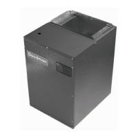
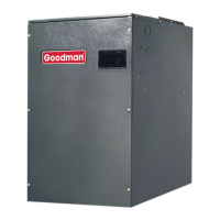
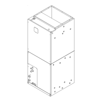
MBR/MBE blower cabinets are engineered to serve as a two-piece blower and coil combination. These blower sections are designed to attach to cased evaporator coils, offering a flexible arrangement that accommodates various mix-matching possibilities. This modular design enhances versatility in installation. The units can be positioned for upflow, counterflow, horizontal right, or horizontal left operation, making them adaptable to diverse installation requirements.
The MBE blower cabinet incorporates a variable speed motor, which is capable of maintaining a constant airflow even with higher duct static pressure. This feature makes it suitable for applications with cooling coils operating at up to 0.8 inches W.C. external static pressure. Additionally, the MBE blower includes a feature that allows for airflow adjustments of ±15%, providing fine-tuning capabilities for optimal performance.
In contrast, the MBR blower cabinet utilizes a PSC (Permanent Split Capacitor) motor. It is approved for applications with cooling coils operating at up to 0.5 inches W.C. external static pressure.
Both MBR/MBE blower cabinets are intended for use with a cased evaporator coil and either a condensing unit or a heat pump. Beyond their primary function, the blower section of these cabinets can also be configured as an electric furnace. Electric heating elements are designed for field installation, and electric heater kits (HKR) are available as sales accessories to provide supplemental electric heat.
The CAPX/CHPX coils, when used with these blowers, are equipped with a thermostatic expansion valve that includes a built-in internal check valve for refrigerant metering. The CACF/CAPF/CHPF coils, on the other hand, are equipped with a fixed restrictor orifice. The coils themselves are designed for various orientations, including upflow, counterflow, or horizontal application. They are compatible with two-speed direct drive motors on CACF/CAPX/CAPF/CHPF/CHPX models, and BPM (Brushless Permanent Magnet) or ECM motors on MBE models.
Usage Features
The manual emphasizes several key aspects for proper usage and installation. Technicians are directed to consult Service Manual RS6100004 for comprehensive installation, operation, and troubleshooting information. This ensures that all procedures are followed correctly to maintain the unit's integrity and performance.
Product identification is crucial for requesting service or parts. The model number, which is broken down into various segments (Design Series, Motor Type, Airflow Delivered, Factory Heat, Circuit Breaker, Electrical Supply), allows for positive identification of component parts used in manufacturing. This detailed breakdown helps in accurately specifying parts and services required.
The units are constructed with R-4.2 insulation, contributing to their energy efficiency. In regions with consistently high humidity (greater than 80%), it is recommended to insulate the exterior of the blower with insulation that has a vapor barrier equivalent to ductwork insulation, provided local codes permit. This helps prevent moisture-related issues and ensures optimal performance in challenging environments.
The manual includes detailed wiring diagrams for various configurations, such as cooling units with optional heat kits (10KW and below, 15KW and above), heat pumps with single or two-stage heating (with options for emergency heat), and two-speed cooling with conventional two-stage thermostats. These diagrams are critical for correct electrical connections and ensuring the safe operation of the unit. It is explicitly stated that wiring is subject to change, and technicians must always refer to the most up-to-date wiring diagram on the unit itself.
The blower performance data is provided in tables, outlining SCFM (Standard Cubic Feet per Minute) at different static pressures and speeds (High, Medium, Low) for MBR models. For MBE models, DIPSWITCH functions are detailed, allowing technicians to adjust CFM output based on electric heat, indoor thermostat settings, cooling and heat pump CFM, and CFM trim adjustments. The "Fan Only" mode for MBE models outputs 30% of the cooling setting, and minor CFM adjustments can be made via dipswitch combinations.
Maintenance Features
Safety is a paramount concern in the maintenance and servicing of these units. The manual includes prominent warnings about high voltage, instructing technicians to disconnect ALL power before servicing or installing the unit. It highlights that multiple power sources may be present, and failure to disconnect them can lead to property damage, personal injury, or death.
All safety information provided in the Service Manual must be strictly followed. Technicians are also advised to refer to the appropriate Parts Catalog for part number information, which is essential for ordering correct replacement parts during maintenance.
Installation and repair of these units must be performed ONLY by individuals meeting the requirements of an "entry level technician" as specified by the Air-Conditioning, Heating and Refrigeration Institute (AHRI). Attempting to install or repair without such a background may result in product damage, personal injury, or death. Goodman explicitly states it will not be responsible for any injury or property damage arising from improper service or service procedures. Many jurisdictions require a license to install or service heating and air conditioning equipment, underscoring the importance of qualified personnel.
Environmental regulations are also addressed. The United States Environmental Protection Agency (“EPA”) has issued various regulations regarding the introduction and disposal of refrigerants used in these units. Failure to comply with these regulations can harm the environment and lead to substantial fines. Technicians are advised to contact their local EPA office for specific jurisdictional requirements.
To prevent property damage, personal injury, or death, combustible materials, gasoline, or other flammable liquids or vapors must not be stored in the vicinity of the appliance. Furthermore, technicians are warned against connecting or using any device not design certified by Goodman for use with the unit, as this can result in serious property damage, personal injury, reduced unit performance, and/or hazardous conditions.
A troubleshooting guide is provided for encoded two-stage cooling thermostats. This guide helps diagnose issues by correlating test indications from the thermostat's LED lights with specific functions and signal outputs. By connecting a test lead or jumper wire from the test terminal to other terminals on the variable speed terminal board, technicians can observe LED lights to verify proper input signals and corresponding output responses. This method allows for easy verification of operation without the need for a multi-meter, facilitating efficient troubleshooting during maintenance and check-out procedures. For instance, if the system calls for first-stage cooling, connecting the test terminal to the "S1" terminal should illuminate the red "+" LED, indicating proper input, and a "YCON" signal should be sent to the condensing unit, resulting in an illuminated "LOW" LED and 24V to the low capacity contactor. This systematic approach ensures that each mode of operation is verified during installation and maintenance.