Do you have a question about the Goodman MBVC RT6223003 and is the answer not in the manual?
Overview of MBVC Blowers, including references for installation, operation, and troubleshooting.
Detailed explanation of the MBVC model number structure and its component designations.
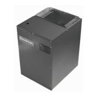
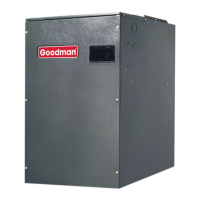
Describes the MBVC blower cabinets' use in two-piece combinations and as electric furnaces.
Explains the ComfortNet™ system, its digital communication, and comparison to traditional systems.
Provides physical data, dimensions, and shipping weight for MBVC blower models.
Illustrates blower opening dimensions for small, medium, and large configurations.
Details allowable combinations of MBVC blowers with various HKR heater kits.
Presents blower performance data including HTR kW, CFM, and switch settings for cooling.
Illustrates wiring diagrams for thermostats connected to modular blowers with AC and HP units.
Details the wiring for the integrated control module, including ECM motor and transformer connections.
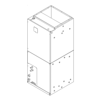
The MBVC Blower is a modular blower cabinet designed for use in split air-conditioning systems. It functions as the indoor component when combined with a cased evaporator coil, forming a two-piece blower and coil combination. This setup can be matched with a remote condensing or heat pump unit, offering various mix-matching possibilities. Additionally, the blower cabinet can operate as an electric furnace when an electric heater is installed.
The MBVC Blower cabinets are primarily used as the indoor section of a split air-conditioning system. They are designed to work with cased evaporator coils to provide cooling and, when equipped with an electric heater kit, heating. The unit utilizes a variable speed ECM motor to maintain a constant airflow, even with varying duct static pressures. It is approved for applications with cooling coils up to 0.8 inches W.C. external static pressure. A key feature is the ability to adjust airflow by ±10%.
The MBVC Blower is part of the ComfortNet™ family of products, enabling it to be installed as either a "legacy" system with a standard 24 VAC thermostat or as a digitally communicating system with a CTK01AA ComfortNet™ thermostat kit. In a ComfortNet™ system, the indoor unit, outdoor unit, and thermostat communicate digitally in a two-way manner, providing automatic airflow configuration, enhanced setup features, and advanced diagnostics. This digital communication also reduces the number of thermostat wires required to a maximum of four.
The MBVC blower models are identified by a specific nomenclature: MBVC1200AA-1AA, MBVC1600AA-1AA, and MBVC2000AA-1AA.
| MODEL | Blower Wheel (D x W) | Blower Motor (HP) | MCA¹ | MOP¹ | Dimensions, inches (mm) W | Dimensions, inches (mm) H | Dimensions, inches (mm) D | Shipping Weight lbs.(kg) |
|---|---|---|---|---|---|---|---|---|
| MBVC1200 | 10X8 | 1/2 | 4.3 | 15 | 17½ (445) | 26 (660) | 21 (533) | 72 (32.6) |
| MBVC1600 | 10X8 | 3/4 | 6.3 | 15 | 21 (533) | 30 (762) | 21 (533) | 82 (37.2) |
| MBVC2000 | 11X10 | 3/4 | 5.8 | 15 | 24½ (622) | 30 (762) | 21 (533) | 94 (42.6) |
| ¹ Minimum Circuit Ampacity (MCA) and Maximum Overcurrent Protection (MOP) for blower without supplemental heat installed. Refer to unit nameplate for MCA and MOP with approved accessory heaters installed. |
The MBVC blowers are compatible with various HKR heater kits (e.g., HKR-03, HKR05, HKR-06, HKR-08, HKR-10, HKR-15C, HKR-20C, HKR-21C). Compatibility varies by model and specific heater kit. "X" indicates allowable combinations, while "~" indicates restricted combinations. Circuit breaker options ("C") are available for some heater kits.
The performance data table provides CFM values for different HTR kW settings across the MBVC1200, MBVC1600, and MBVC2000 models. It also specifies DIP switch settings (SWITCH 9, 10, 11) for each configuration.
The blower speed selection DIP switches on the integrated control module allow for setting "cooling" speed taps (switches 1 and 2) and "adjust" taps (switches 3 and 4).
All models operate on 208-230V/60HZ/1 phase. The unit includes a 40 VA transformer for 24 VAC control. Fuses: 24V/3A.