40 GOSSEN METRAWATT GMBH
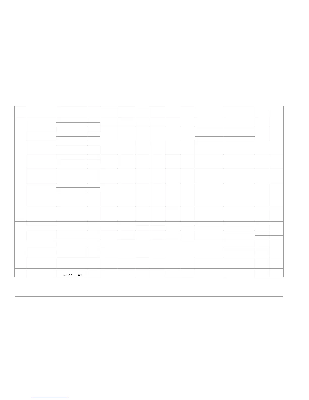
16 Characteristic Values
1)
The device leakage current step of the test sequence is executed by means of
differential current measurement for testing per DIN VDE 0751.
2)
As of 25 mA: shutdown by residual current measurement within 100 ms
3)
Measured value P and calculated value S are compared and the smaller of the two is displayed.
4)
Measuring circuit becomes highly resistive, indication at display
5)
For DIN VDE 0701/0702: 2 kΩ, for DIN VDE 0751: 1 kΩ
6)
This measuring range with DIN VDE 0751 only
Func-
tion
Measured Quantity Measuring Range /
Nominal Range of
Use
Resolu-
tion
Nominal
Voltage
U
N
Open-Cir-
cuit Volt-
age U
0
Nominal
Current
I
N
Short-
Circuit
Cur. I
K
Internal
Resis-
tance R
I
Reference
Resist.
R
REF
Measuring
Error
Intrinsic Error Overload Capacity
Value Duration
Tests per DIN VDE 0701 / 0702 / 0751
Device Protective
Conductor
Resistance R
PE
0.000 … 2.100 Ω 1mΩ
—
4.5 … 9V
DC
—
>200 mA
DC
——
±(5% rdg. + 10 d)
>10d
±(2.5% rdg. + 5d)
> 10 d
253 V cont.
2.11 … 31.00 Ω 10 mΩ
0.050 … 1.500 MΩ 1kΩ
50 … 500
VDC
1.0 • U
N
…
1.5 • U
N
>1mA <10mA — —
±(5% rdg. +10 d)
±(2.5% rdg. +5 d)
> 10 d
253 V cont.
Insulation Resistance
R
ISO
1.01 … 10.00 MΩ 10 kΩ
10.1 … 310.0 MΩ 100 kΩ±(10% rdg. +10 d) ±(10% rdg. +10d)
Equivalent Leakage
Current
I
EL
or. I
DL
0.00 … 21.00 mA 10 μA
—
230 V~
– 20/
+10 %
— < 3.5 mA > 72 kΩ 1/2 kΩ
5
±(5% rdg. +10 d)
±(2.5 % rdg. +5 d)
> 10 d
253 V cont.
20.1 … 120.0 mA 100 μA
Equivalent Patient
Leakage Current
I
EPL
0.0 ... 310.0 μA100nA
—
230 V~
– 20/
+10 %
— < 3.5 mA > 72 kΩ
1kΩ
±10 Ω
±(5% rdg. +10 d)
±(2.5% rdg. +5 d)
> 10 d
253 V cont.0.300 ... 2.100 mA 1 μA
2.00 ... 11.00 mA 10 μA
Contact Current or
Housing Leakage
Current I
Probe
or I
DL
0 … 310 μA
6
0.300 … 3.500 mA
0.1 μA
1 μA
————1/2kΩ
5
— ±(5% rdg. +10 d)
±(2.5% rdg. +5 d)
> 10 d
253 V cont.
Patient Leakage
Current I
PL
AC/DC Compo-
nents Measured
Separately
0.0 ... 310.0 μA100nA
————1kΩ — ±(5% rdg. +10 d)
±(2.5% rdg. +5 d)
> 10 d
253 V
cont.
2 4
0.300 ... 3.100 mA 1 μA
3.10 ... > 15.00 mA 10 μA
Differential
Current ΔI
between L and N
1
0.000
…
3.100 mA
~
3.00 … 31.00 mA~
2
1 μA
10 μA
— — ————
±(10% rdg. +10 d)
> 10 d
±(5% rdg. +5 d)
> 10 d
22
Function Test
Line Voltage U
L–N
207.0 ... 253.0 V~ 0.1 V — — — — ±(2.5% rdg. +5 d) 253 V cont.
Load Current I
V
0 ... 16.00 A
RMS
10 mA — — — — ±(2.5% rdg. +5 d) 20 A 10 min.
Active Power P 0 ... 3700 W
3
1W — — — —
±(5% rdg. +10 d)
>20d
253 V cont.
20 A 10 min.
Apparent Power S 0 ... 4000 VA 1 VA Calculated value U
L–N
• I
V
±(5% rdg. +10 d)
>20s
Power Factor LF,
sinusoidal: cos
ϕ
0.00 ... 1.00 0.01 Calculated value P / S, display > 10 W ±(10% rdg. +5 d)
Differential Current
ΔI between L and N
per DIN VDE 0702
0.00 ... 31.00 mA~ 10 μA———
±(10% rdg. +10 d)
> 10 d
±(5% rdg. +5 d)
22
U
Probe
Probe voltage
0 ... 253.0 V
, and
0.1 V — — —
±(2.5% rdg. +5 d)
>10d
253 V cont.
 Loading...