3
INSTALLATION
Before installing your meter, review
the safety instructions given above�
Examine your meter to make sure
there are no visible signs of shipment
damage� Plan your meter installation
by reviewing the following procedures�
Your system must be mounted on a
vented tank� If the tank is unvented,
your local dealer or distributor can
supply a pressure cap�
If the meter is located in a rigid piping
system where the fluid is trapped
(for example, by gravity, valves or
nozzles) thermal expansion of the uid
can create pressure spikes that can
damage a meter� Install a thermal relief
valve or otherwise allow for thermal
expansion of the uid�
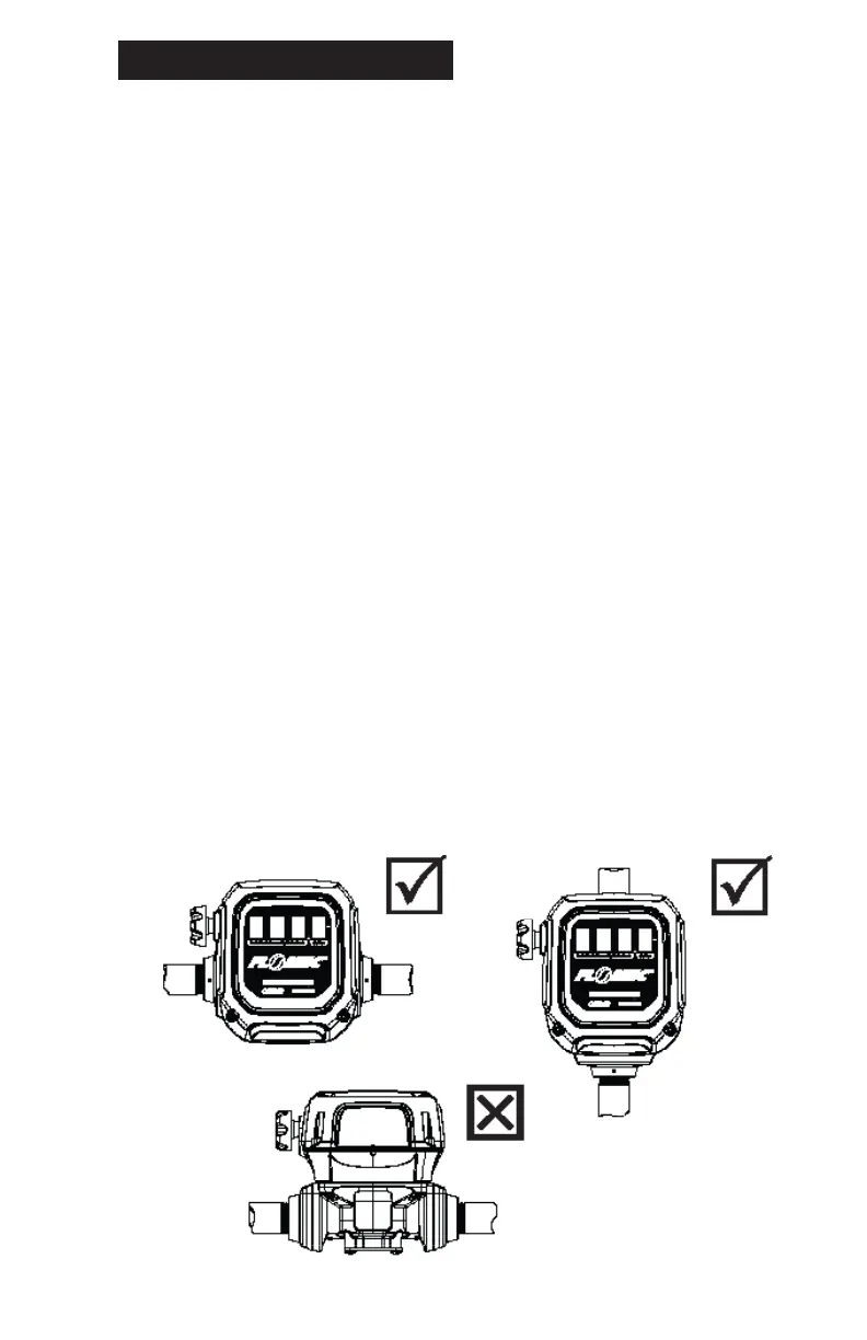
The owmeter MUST be mounted so
that the rotor shafts are in a horizontal
plane� Mounting the meter with the
mechanical display facing horizontally
will orient the rotor shafts correctly�
The mechanical display should never
face upwards or toward the ground�
The weight of the rotors must be
supported by the horizontal rotor shafts�
If installed incorrectly, performance,
life or accuracy could be affected�
(see Figure 1)
Liquid can ow in a horizontal direction,
or a vertical direction, but in each case
the rotor shafts must be in a horizontal
plane�
It is preferred to install the ow-meter
upstream of a ow control or shut-off
valve, as the back pressure provided
by the valve will be benecial to system
accuracy� The flow meter should
remain full of liquid at all times when
connected�
Do not operate the ow-meter directly
discharging to the atmosphere�
Prior to installation, determine whether
horizontal or vertical ow is required�
For vertical ow installations the liquid
should travel from bottom to top, i�e�
it should rise vertically through the
ow-meter� This will ensure that the
ow-meter remains full of liquid, and
will prevent air entrapment in the meter�
The back of the meter housing is
embossed with “INLET” and “OUTLET”
adjacent to its respective port to assist
in correct piping connections�
gure 1
Correct
Horizontal Flow
Vertical Flow
InCorrect
Correct

 Loading...