14
3.4 Wall and Pipe Mounting
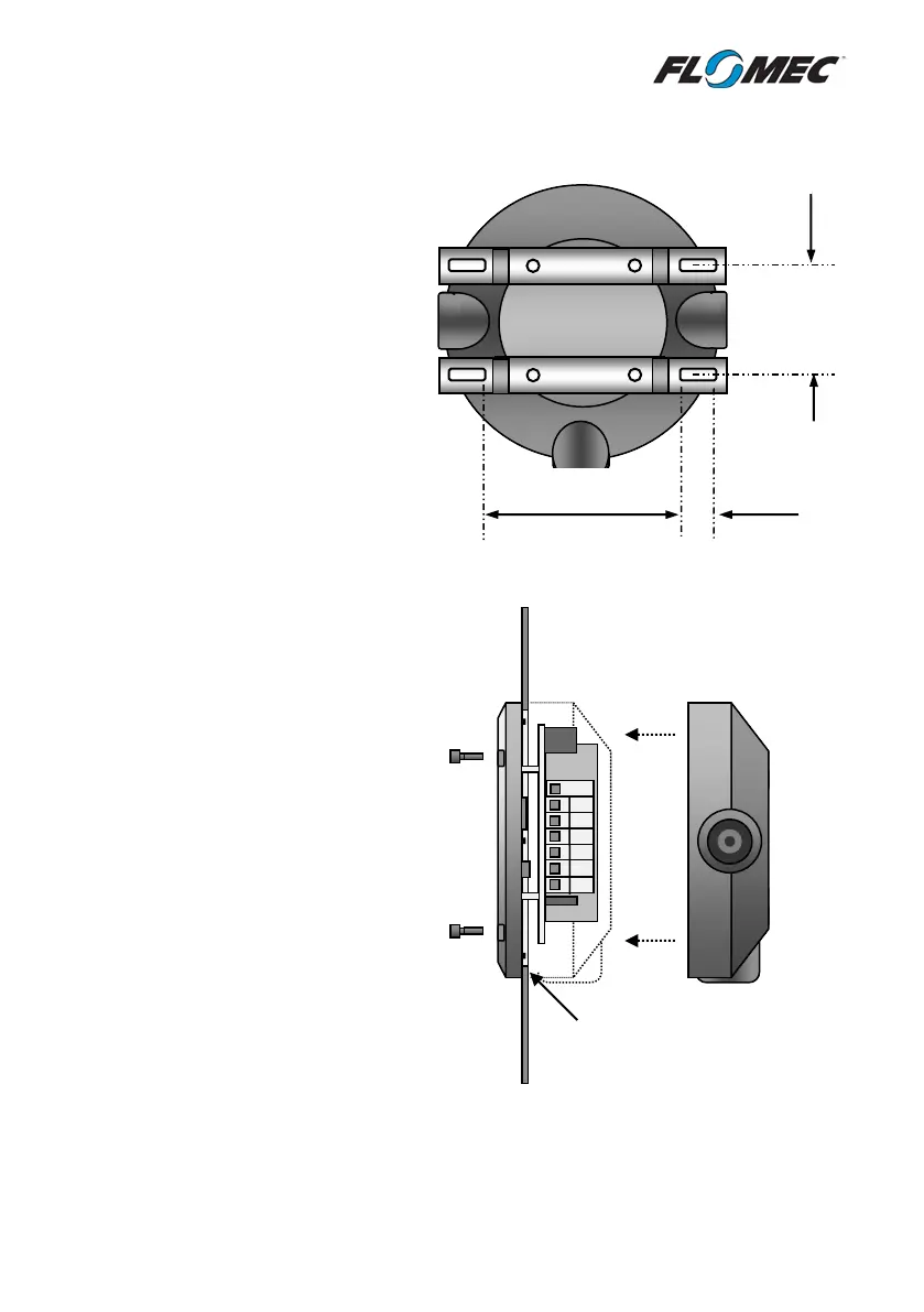
3.5 Panel Mounting
diameter hole in panel
Mounting of the instrument in a panel
requires a 106.5mm – 107.8mm (4.20” -
4.25”) round hole to be cut in the panel.
Up to a 109mm (4.30”) is suitable if the
IP65 rating is not required.
The rear enclosure of the instrument can
be mounted behind the panel (as per
diagram to the right) to protect the back of
the electronics module if required,
however this is not compulsory.
When panel mounted the IP rating of the
instrument is reduced to IP65 on the front
side of the panel only – with the rear
enclosure mounted behind the panel the
back side of the instrument will have an
IP20 rating.
” )
” )
Mounting of the instrument on
a pipe or flat surface (such as a
wall) can be accomplished using
the ‘Wall Mount Kit’, or ‘Pipe
Mount Kit’ available from the
manufacturer.