EasyManua.ls Logo

Graco 234114 - User Manual

Graco 234114
6 pages
Print Icon
To Next Page IconTo Next Page
Loading...
Metered Dispensing Valve
For metered dispense of petroleum and synthetic oils. 309583 rev.B
1000 psi (7 MPa, 69 bar) Maximum Working Pressure
4 gpm (15.1 lpm) Maximum Flow Rate
Model 234114, Series A (1–16 quarts)
Model 253601, Series A (1–10 liters)
Table of Contents
Symbols and Warnings 2. . . . . . . . . . . . . . . . . . . . . . . . . .
Operation 3. . . . . . . . . . . . . . . . . . . . . . . . . . . . . . . . . . . . .
Service 4. . . . . . . . . . . . . . . . . . . . . . . . . . . . . . . . . . . . . . .
Parts 4. . . . . . . . . . . . . . . . . . . . . . . . . . . . . . . . . . . . . . . . .
Dimensions 4. . . . . . . . . . . . . . . . . . . . . . . . . . . . . . . . . . . .
Graco Warranty 6. . . . . . . . . . . . . . . . . . . . . . . . . . . . . . . .
Graco Information 6. . . . . . . . . . . . . . . . . . . . . . . . . . . . . .
Instructions
GRACO INC.ąP.O. BOX 1441ąMINNEAPOLIS, MNą55440-1441
Copyright 2002, Graco Inc. is registered to I.S. EN ISO 9001
Important Safety Instructions.
Read all warnings and instructions in this manual.
Save these instructions.
Parts
Question and Answer IconNeed help?

Do you have a question about the Graco 234114 and is the answer not in the manual?

Overview

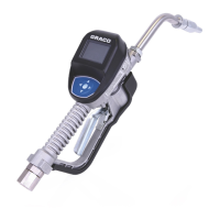
The Graco Metered Dispensing Valve is a specialized device designed for the metered dispense of petroleum and synthetic oils. This manual, identified as 309583 rev.B, provides instructions for its operation, service, and parts.

Function Description

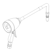
The primary function of the Metered Dispensing Valve is to accurately dispense a predetermined amount of petroleum and synthetic oils. It features a meter dial that allows users to monitor the dispensed quantity and a totalizer that keeps a running total of all amounts dispensed. The valve is designed for professional use, ensuring precise fluid delivery in various applications.

Important Technical Specifications

The Metered Dispensing Valve boasts several key technical specifications:

  • Maximum Working Pressure: 1000 psi (7 MPa, 69 bar). It is crucial not to exceed the maximum working pressure of the lowest-rated system component to prevent equipment rupture or malfunction.
  • Maximum Flow Rate: 4 gpm (15.1 lpm). This indicates the maximum volume of fluid the valve can dispense per minute.
  • Models:
    • Model 234114, Series A: Dispenses in a range of 1–16 quarts.
    • Model 253601, Series A: Dispenses in a range of 1–10 liters.
  • Dimensions:
    • Length (from nozzle tip to handle base): 10.25 inches (260 mm).
    • Height (from top of meter to bottom of handle): 10.5 inches (267 mm).
    • Width: 3.84 inches (97.5 mm).
  • Weight: 4 lb. (1.8 kg).
  • Inlet/Outlet Connections: 1/2 npt (National Pipe Taper) for fluid connections.
  • Included Parts:
    • SWIVEL, 1/2 bsp(m) x 1/2 npt(f) (Part No. 117675): This swivel allows for flexible connection to the fluid supply.
    • EXTENSION, hose w/manual shut off nozzle (Part No. 117676): This extension provides reach and includes a manual shut-off nozzle for controlled dispensing.

Usage Features

The Metered Dispensing Valve is designed for straightforward and safe operation:

  • Dispensing Procedure:
    1. Insert the nozzle into the fluid receptacle.
    2. Pull the trigger to begin dispensing.
    3. Monitor the meter pointer on the dial and release the trigger when the desired amount of fluid has been dispensed.
    4. Before the next dispense, return the meter pointer to "O" to ensure accurate measurement.
  • Safety Instructions: The manual emphasizes several critical safety warnings:
    • Equipment Misuse Hazard: Misuse can lead to equipment rupture or malfunction and serious injury. Users are advised to read all manuals, tags, and labels, use the equipment only for its intended purpose, and avoid alterations or modifications.
    • Skin Injection Hazard: Spray from the valve, leaks, or ruptured components can inject fluid into the body, causing extremely serious injury, including the need for amputation. Users must never point the valve at anyone, place hands over the nozzle, or attempt to stop leaks with body parts or rags. Immediate surgical treatment is required for any fluid injection.
  • Pressure Relief Procedure: This procedure is essential before any cleaning, checking, or servicing of the equipment to prevent injury from pressurized fluid. It involves:
    1. Turning off the power supply to the pump.
    2. Triggering the valve into a waste container to relieve pressure.
    3. Opening any bleed-type master air valves and fluid drain valves in the system.
    4. Leaving drain valves open until repairs are complete and the system is ready for repressurization.
  • Meter Pointer Reset: The meter pointer must be returned to "O" before each dispense to ensure accurate readings. A caution warns against turning the pointer backward to avoid costly meter damage.
  • Totalizer: The valve includes a totalizer that continuously tracks the cumulative amount of fluid dispensed, providing a running record.

Maintenance Features

Regular maintenance is crucial for the longevity and accurate performance of the Metered Dispensing Valve:

  • Regular Cleaning: The inlet screen should be cleaned regularly to prevent blockages and maintain optimal flow.
  • Meter Cleaning Procedure: A detailed procedure is provided for cleaning the meter components:
    1. Unscrew the meter cap (G) from the housing (A).
    2. Remove the o-ring (F), piston and chamber assembly, and the planet gear.
    3. Insert a screwdriver into the notch of the chamber assembly and pry off the chamber top (B).
    4. Remove all internal parts.
    5. Clean all parts thoroughly and blow them dry.
    6. Reassemble the meter, ensuring the piston chamber slot (E) straddles the partition plate (D).
    7. Install the top chamber (B) and turn the small gear until the piston (C) engages with the pawl.
    8. Place the piston and chamber assembly into the housing and turn it to confirm proper gear mesh.
    9. With the o-ring (F) in place, firmly tighten the cap (G) into the housing (A).
  • Hose and Coupling Inspection: Daily checks of hoses, tubes, and couplings are recommended. Worn or damaged parts must be replaced immediately. High-pressure couplings should not be repaired; the entire hose must be replaced if damaged.
  • Warranty: Graco provides a standard warranty covering defects in material and workmanship for twelve months from the date of sale. This warranty is conditional on proper installation, operation, and maintenance according to Graco's recommendations. It does not cover general wear and tear, misuse, faulty installation, or incompatible components.

Graco 234114 Specifications

General IconGeneral
BrandGraco
Model234114
CategoryControl Unit
LanguageEnglish

Related product manuals