Repair
14 308485R
Reassembly
Ensure that all necessary parts are on hand. Air Motor
Repair Kit 207385 includes repair parts for the motor.
For best results, use all of the parts in the kit. Parts
included in the kit are marked with an asterisk in the
text and drawings, for example (19*). See Air Motor
Parts List, page 19.
1. Place the piston rod (29) flats in the vise with the air
motor facing up.
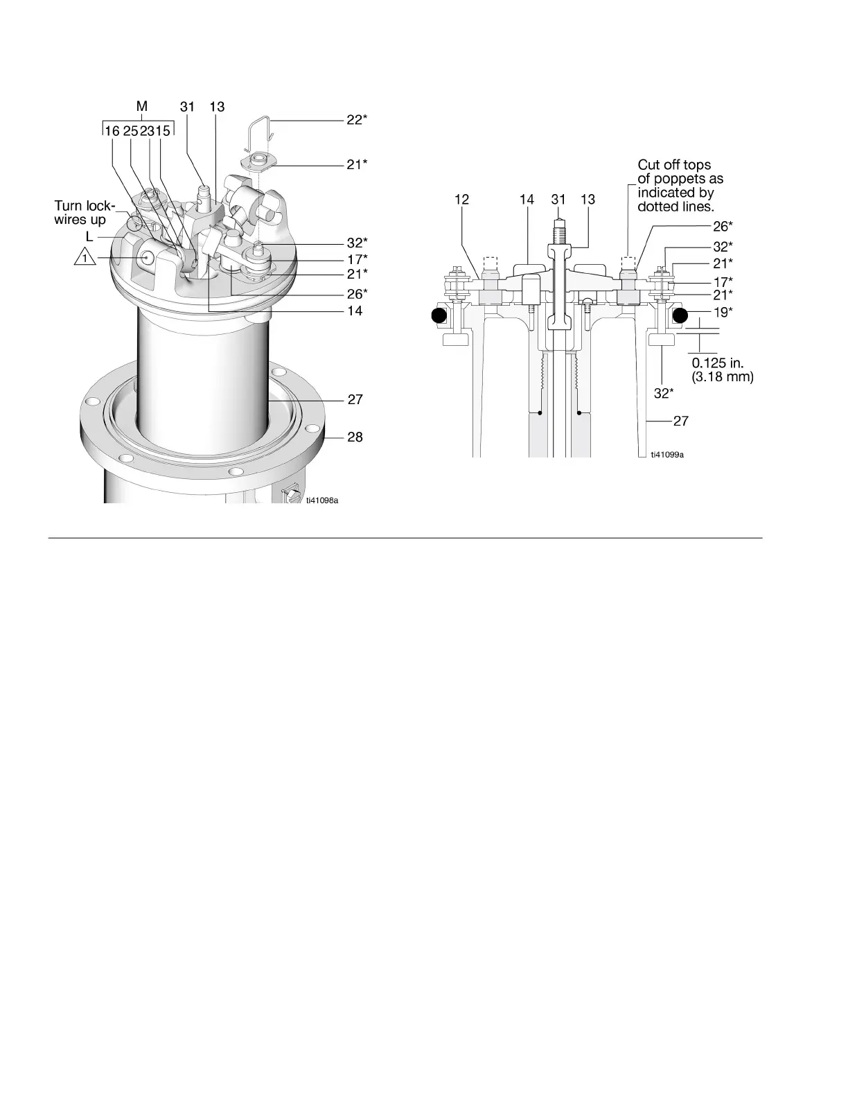
2. Pull the exhaust valve poppets (26*) into the valve
actuator (12), and clip off the top parts of the
poppets (shown with dotted lines in the Cutaway
View in F
IG. 4).
3. Install the grommets (17*) in the actuator (12), place
the inlet valve poppets (32*) in the piston, and
thread the bottom valve nuts (21*) onto the inlet
valve poppets until there are a few threads left
before the threads run out.
NOTE: If the valve nuts are threaded too far down onto
the poppets, they will run off of the threaded part of the
poppets.
4. Grease heavily and place the trip rod (31) in the
piston, place the actuator (12) in the yoke (13), and
place the well-greased actuator/yoke assembly in
the piston, with the trip rod going through the
center holes of the actuator and yoke and the inlet
valve poppets (32*) going through the grommets
(17*).
5. Thread the top valve nuts (21*) onto the inlet valve
poppets (32*) until one thread of the inlet valve
poppets is exposed above the valve nuts.
6. Install the toggle pins (15) in the yoke (13), place the
toggle arm (23) ends of the toggle assembly (M)
onto the toggle pins, and snap the pivot pin (16)
ends of the toggle assembly into the lugs (L).
7. Measuring with the gauge (Part No. 171818), create
0.125 in. (3.18 mm) of clearance between the inlet
valve poppets (32*) and the piston seat when the
inlet valve is open. See the Cutaway View in F
IG. 4.
NOTE: Adjust the distance between the inlet valve
poppets and the piston seat by turning the top valve
nuts (21*).
8. Hand-tighten the bottom valve nuts (21*) securely.
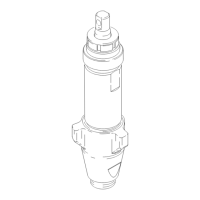
FIG. 4 Air Motor and Throat
Cutaway View