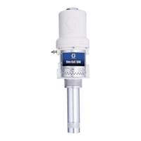
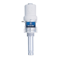
Installation
308883W 3
Installation
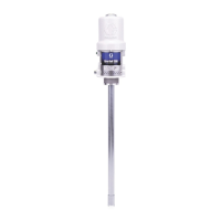
Grounding
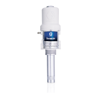
Pump: Use a ground wire and clamp as shown in FIG.
1.
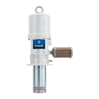
Fluid hoses: Use only electrically conductive hoses.
Air compressor: Follow manufacturer’s recommenda-
tions.
Fluid supply container: Follow the local code.
To maintain grounding continuity when flushing or
relieving pressure: hold metal part of the spray
gun/dispense valve firmly to the side of a grounded
metal pail, then trigger the gun/valve.
To ground the pump: remove the ground screw (Z)
and insert through the eye of the ring terminal at end of
the ground wire (Y). Fasten the ground screw back onto
the pump and tighten securely. Connect the other end
of the ground wire to a true earth ground. See Fig. To
order a ground wire clamp, order Part. No. 222011.
Key:
A Fluid dispense line
B Pump ground wire (required)
C Air regulator with gauge
D Main air supply line
E Air line filter
F Air line lubricator
G Pump runaway valve
H Follower plate
J Bleed-type master air valve (required)
K Fluid drain valve
The equipment must be grounded to reduce the risk
of static sparking and electric shock. Electric or
static sparking can cause fumes to ignite or explode.
Improper grounding can cause electric shock.
Grounding provides an escape wire for the electric
current.
FIG. 1
Y
Z
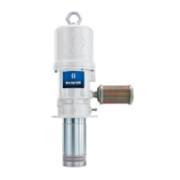
FIG. 2: Typical Installation
Recommended air line
configuration to reduce
moisture in pump
1/2 in.
B
C
D
E
F
G
H
J
A
J
K

 Loading...