06538C
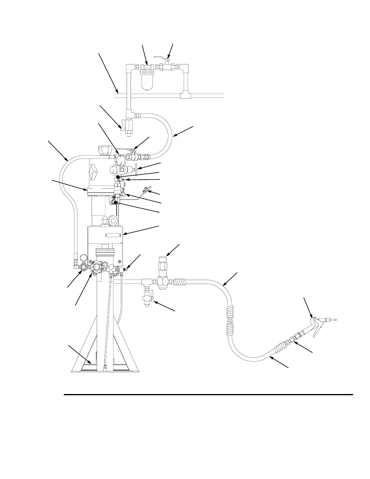
Fig. 2
MAIN AIR LINE
KEY
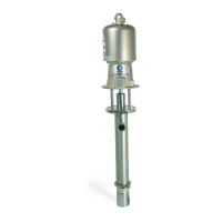
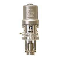
A Pump
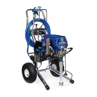
B 19 Liter (5 Gallon) Air-Powered Ram
C Wiper Plate
D Air Manifold
E Pump Runaway Valve (location shown)
F Air Line Lubricator (location shown)
G Pump Bleed-Type Air Valve (required, for pump)
H Pump Air Regulator
J Air Line Filter
K Bleed-Type Master Air Valve (for accessories)
L Fluid Drain Valve (required)
M Fluid Pressure Regulator
N Airless Spray Gun or Dispensing Valve
P Gun/Valve Swivel
Q Air Pressure Relief Valve
R Electrically Conductive Fluid Supply Hose
S Electrically Conductive Air Supply Hose
T Ram Air Regulator
U Ram Director Valve
V Red–Handled Main Air Bleed Valve
W Air LIne Drain Valve
X Air Release Valve
Y Ground Wire (required, see page 7 for
installation instructions)
Z Electrically Conductive Fluid Whip Hose
A
B
D
E
F
Q
JK
Y
R
T
L
N
P
S
M
C
W
H
S
U
X
V
Z
G
308026 9
Setup