Do you have a question about the Graco Merkur and is the answer not in the manual?
Details fire and explosion risks associated with flammable fumes and static sparking.
Explains risks from pressurized fluid leaks or component rupture.
Covers risks from operating equipment while impaired or exceeding limits.
Warns about hazards from moving components that can cause injury.
Details dangers from toxic fluids or fumes through contact, inhalation, or ingestion.
Emphasizes wearing appropriate protective gear to prevent injury.
Outlines conditions to avoid hazardous situations like fire or explosion.
Lists and defines components shown in the typical installation diagram.
Provides general notes and recommendations for system setup.
Details operator training, site cleanliness, and air supply requirements.
Instructions for mounting the pump and ensuring spray booth ventilation.
Lists and describes the various parts included in the system.
Critical safety procedure for preventing static shock and ignition.
Step-by-step instructions for connecting hoses and regulators.
Step-by-step guide to relieve system pressure before servicing.
Instructions for flushing the equipment with solvent before initial use.
Instructions for filling and maintaining the wet cup.
Key operational step to fill the pump and lines with fluid.
Specific setup instructions for the electrostatic air spray gun.
Procedure for safely turning off and securing the equipment.
Guidance on establishing a regular maintenance schedule.
Instructions for checking hoses and connections for leaks.
Detailed procedure for flushing the pump with cleaning fluid.
Instructions for filling and maintaining the wet cup.
Describes the operational status and display in Run Mode.
Details how to navigate and configure settings in Setup Mode.
Explains pump runaway and how to reset the system.
Instructions for entering and exiting the Prime/Flush mode.
How to view and reset batch and grand totalizers.
Information about the DataTrak display behavior.
How to view and acknowledge diagnostic codes.
Step-by-step guide for replacing the DataTrak battery.
Instructions for replacing the fuse in the DataTrak module.
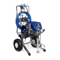
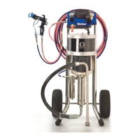
Illustrates and labels parts for the cart-mounted configuration.
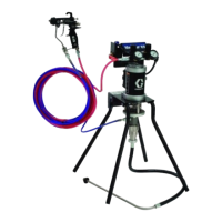
Illustrates and labels parts for the wall-mounted configuration.
Lists components included in the wall mount kit.
Lists components included in the cart mount kit.
Details components for pump and gun control panel kits.
Lists parts for mounting air controls.
Note directing users to a separate manual for DataTrak details.
Lists components included in the drain valve kit.
Provides dimensions and hole layout for the wall bracket.
| Fluid Delivery | Up to 4.0 gpm (15.1 lpm) |
|---|---|
| Air Inlet Size | 1/4 in npsm |
| Fluid Inlet Size | 1/2 in npsm |
| Fluid Outlet Size | 1/4 in npsm |
| Maximum Air Input Pressure | 100 psi (0.7 mpa) |
| Maximum Fluid Pressure | up to 3300 psi (22.7 mpa) |
| Pump Type | Air-Operated Piston Pump |
| Flow Rate | up to 4.0 gpm (15.1 lpm) |
| Power | Air operated |
| Inlet/Outlet Size | Fluid Inlet: 1/2 in npsm, Fluid Outlet: 1/4 in npsm |