Typical Installation
3A7004B 11
NOTE: High velocity air exhaust will decrease the oper-
ating efficiency of the electrostatic system. Air exhaust
velocity of 100 ft/min (31 linear meters/minute) should
be sufficient.
Components
See FIG. 1. Components vary by package ordered.
See table on page 24. Your package may include:
• A bleed-type master air valve (U) is required in your
system to relieve air trapped between it and the air
motor and gun when the valve is closed. Do not
block access to the valve.
• The pump air regulator (X) controls pump speed
and outlet pressure by adjusting the air pressure to
the pump.
• The air relief valve (not shown) opens automatically
to prevent overpressurization of the pump.
• The gun air regulator (T) adjusts the air pressure to
the electrostatic spray gun (H).
• The electrostatic air spray gun (H) dispenses the
fluid.
• The suction hose (N) with strainer (P) allows the
pump to draw fluid from a 5 gallon (19 liter) pail.
• A fluid filter (F) with a 60 mesh (250 micron) stain-
less steel element filters particles from fluid as it
leaves the pump.
• A fluid drain valve (AC) relieves fluid pressure in the
hose and gun.
• DataTrak (V) provides pump diagnostics and mate-
rial usage information. See page 17.
Air and Fluid Hoses
• The gray hose (AA) provides the gun air supply.
• The blue hose (Z) provides the gun fluid supply.
Grounding
The following are minimum grounding requirements for
a basic electrostatic system. Your system may include
other equipment or objects which must be grounded.
Check your local electrical code for detailed grounding
instructions. Your system must be connected to a true
earth ground.
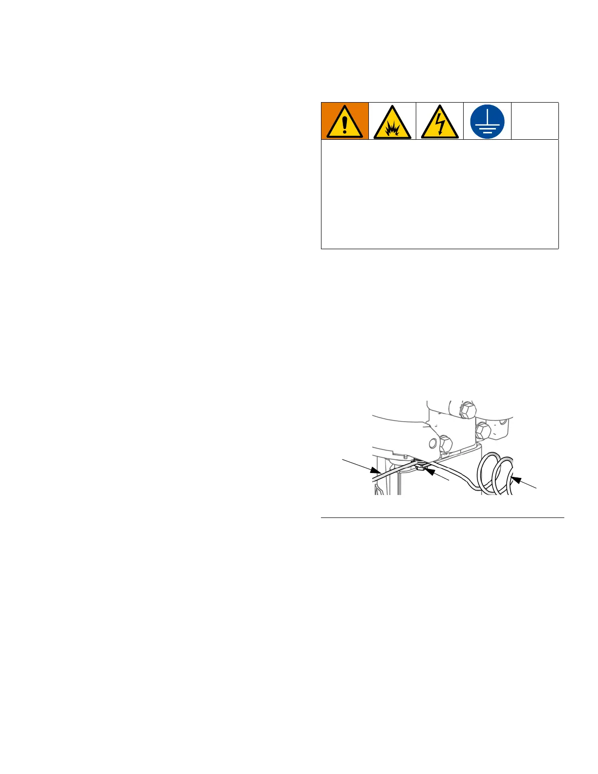
Pump: Verify that the ground screw (GS) is attached
and tightened securely to the air motor. Connect the
other end of the ground wire (R) to a true earth ground.
Electrostatic Spray Gun: Use only the Graco Electri-
cally Conductive Air Supply Hose (supplied). Connect
the Gun Grounding Wire (AC) to the ground screw (GS)
on the air motor.
Air compressor: follow manufacturer’s recommenda-
tions.
All air and fluid lines must be properly grounded. Use
only grounded hoses with a maximum of 500 feet
(150m) combined hose length to ensure grounding con-
tinuity.
Object being sprayed: keep the workpiece hangers
clean and grounded at all times. Follow local code.
When operating the electrostatic gun, any
ungrounded objects in the spray area (people,
containers, tools, etc.) can become electrically
charged.The equipment must be grounded to reduce
the risk of static sparking and electric shock. Electric
or static sparking can cause fumes to ignite or
explode. Improper grounding can cause electric
shock. Grounding provides an escape wire for the
electric current.
F
IG. 2. Ground Screw and Wire

 Loading...