Repair
10 306982ZAE
Reassembly
1. Clean all the parts carefully in a compatible solvent
and inspect for wear or damage. Use all the repair
kit parts during reassembly and replace other parts
as necessary.
2. Check the polished surfaces of the piston, piston
rod and cylinder wall for scratches or wear. A
scored rod will cause premature packing wear and
leaking.
3. Lubricate all parts with a light, waterproof grease.
4. Be sure the o-rings are in place. Slide the piston
rod down through the throat bearing and lower the
piston (Y) into the air motor base (J).
5. Pull the exhaust valve poppets (X**) into the valve
actuator (V) and clip off the top part shown with
dotted lines. See F
IG. 4.
6. Install the transfer valve poppets (R**) onto the
valve stems (O**), then reassemble the valve stems
(O**), bottom adjusting nuts (Q**), grommets (P**),
and top adjusting nuts (M**) on the piston (Y).
Assemble the trip rod (H), valve actuator (V), trip rod
yoke (K) and toggle assemblies (E) on the piston.
See F
IG. 4.
7. Set gap on inlet valve (N) using the 125 in. (3.18
mm) side of gauge 171818. Rotate valve stem (O**)
until snug against gauge, then back off until valve
stem slot is lined up with wire holes in valve nut
(M**) (do not back off more than 1/2 turn). See F
IG.
4 on page 9. Install lockwires (L**) in the adjusting
nuts M** and Q**).
8. Snap the toggle assemblies (E) to the up position.
Reinstall the cylinder (G) and hold the trip rod (H) in
place with tool 207579. Apply a medium strength
thread locking compound to the threads of the trip
rod (H) and assemble the cap nut (F) to the trip rod
(H). Torque the cap nut (F) to 60 lb-in (6.8) N-m).
Install cap nut (F) into cylinder (G).
9. Before remounting the pump, connect an air hose
and run the pump slowly, at about 40 psi (0.28
MPa, 2.8 bar) to ensure that it operates smoothly.
10. Reconnect the ground wire before regular
operation of the pump.
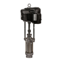
Throat Packing Service for In-Line Pump
Model 205647
NOTE: See FIG. 5 on page 11 and Parts on page 13.
1. Clamp the pump in a vise and unscrew the
displacement cylinder (CC) from the air motor base
(J). Pull the displacement cylinder away from the air
motor until the cotter pin (DD) which secures the
displacement pump connecting rod to the air motor
piston rod (FF) is visible.
2. Remove the cotter pin (DD) and unscrew the pump
connecting rod (EE) from the air motor piston rod
(FF). Remove the cylinder (G) from the air motor
base (J) as described under Disassembly on page
8.
3. Remove one louvered air exhaust plate (BB) and
unscrew the throat packing nut (HH), using a
spanner wrench or a 0.22 in. (5.6 mm) diameter rod.
Remove the spacer and packing from the base and
packing nut. Clean the throat packing area in the
base and the packing nut. Clean and inspect all
parts and replace as necessary.
4. Lubricate the packings, piston rod and piston
flange with a light waterproof grease. Reinstall the
spacer and packing in the base and packing nut.
Be sure the lips of the v-packings face down. See
Detail B. Screw the packing nut loosely into the
base. Carefully slide the piston rod down through
the throat packing and lower the piston into the
base. Tighten the packing nut securely. Reinstall
the plate (BB) and cylinder (G). Reassemble the air
motor to the displacement pump.
To avoid fire and explosion, always ground
equipment and waste container. To avoid static
sparking and injury from splashing, always flush at
the lowest possible pressure.
The piston in the air motor, located behind the air
motor plates, moves when air is supplied to the
motor. Moving parts can pinch or amputate your
fingers or other body parts. Therefore, never operate
the pump with the air motor plates removed.
 Loading...