10
307–785
SETUP
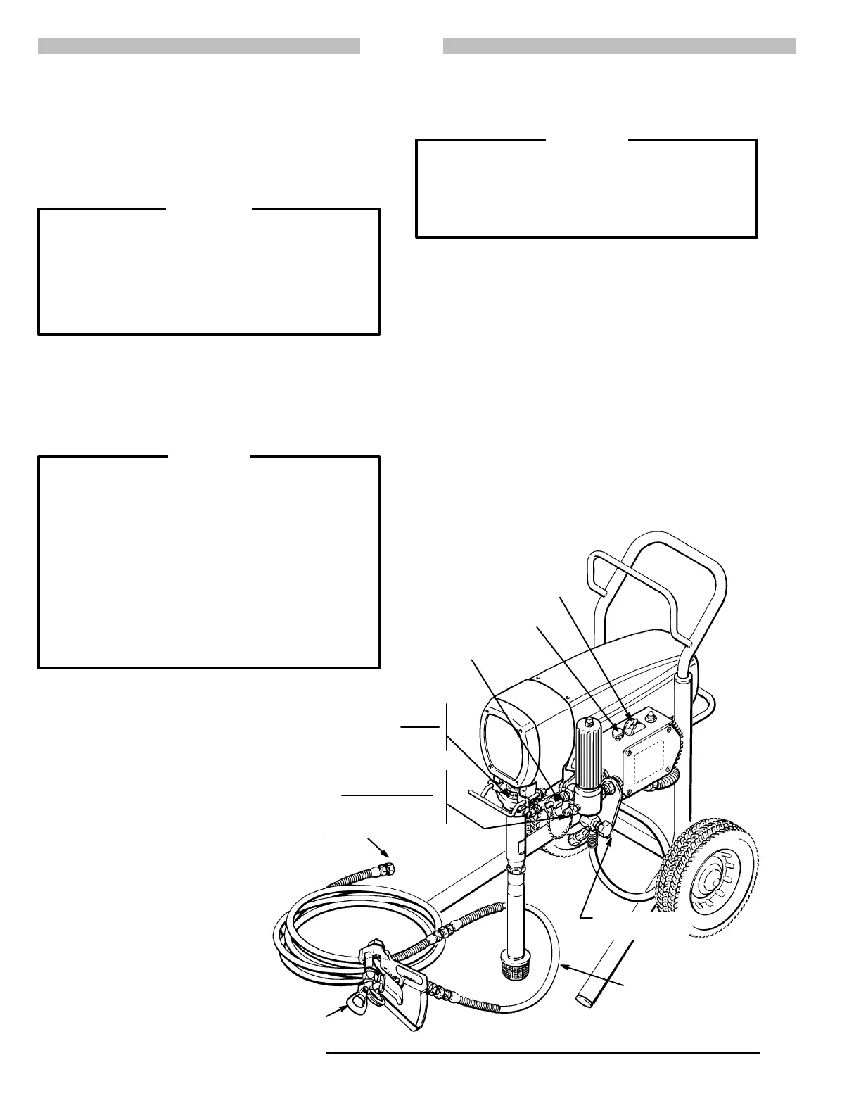
NOTE: Refer
to Fig 10–1 for Steps 1 to 3.
1. Connect Hose and Gun. Connect the gun, 3 ft.
hose and 50 ft. hose. Remove the disposable cap
from the outlet nipple. Screw the gun and hose as-
sembly
onto the nipple.
NOTE: Don’t use thread sealant, and don’t install the
spray
tip yet!
WARNING
If
you supply your own hoses and spray gun, be sure
the hoses are electrically conductive, that the gun
has
a tip guard, and that each part
is rated for at least
3000 psi (210 bar) Working Pressure
. This is to re-
duce
the risk of serious
bodily injury caused by static
sparking, fluid injection or over–pressurization and
rupture
of the hose or gun.
2. Two Gun Hookup. Remove the cap from the 1/4
npsm(m) secondary hose outlet. Connect a hose
and gun to the outlet. Use a 1/4 in. ID, 50 ft. long
(minimum) main hose. For more flexible gun move-
ment,
install a 3/16 in. ID, 3 ft. hose between the main
hose
and the gun.
To
avoid damaging the pressure control, which
may
result in poor equipment performance and compo-
nent
damage, follow these precautions:
1. Always
use nylon spray hose
at least 50 ft. long.
2. Never
use a wire braid hose as it is too rigid
to
act as a pulsation dampener
.
3. Never
install any
shutof
f device between the fil
-
ter
and the main hose.
Refer to Fig 10–1.
4. Always
use the main filter outlet for one gun
op
-
eration.
Never plug this outlet.
CAUTION
3. Fill the Packing Nut/Wet–
Cup. Fill the packing nut/wet–
cup 1/3 full with Graco Throat
Seal
Liquid (TSL), supplied.
4.
Check the Electrical Service.
a.
Be sure the electrical serv-
ice is 120 V , 60 HzAC, 15
Amp (minimum) and that
the outlet you use is prop-
erly
grounded.
b.
Do not remove the third
prong of the power supply
cord,
which is the grounding
prong, and do not use an
adapter.
c. Use an extension cord
which
has 3 wires of a mini
-
mum 12 gauge size, a
maximum of 150 ft. long
and is rated for 15 amps.
Longer lengths may af fect
sprayer
performance.
5.
Plug in the Sprayer . Be sure the ON/OFF switch
is
OFF
. Then plug the cord into a grounded electrical
outlet
at least 20 ft. away from the spray area.
WARNING
Proper electrical grounding is essential to reduce
the
risk of fire
or explosion which can result in seri
-
ous
bodily injury and property damage. Refer to the
warning section
FIRE OR EXPLOSION
HAZARD
on
page 5
for more detailed grounding instructions.
6. Flush
the pump
to remove the lightweight oil which
was
left in to protect pump parts after factory testing.
Refer to FLUSHING GUIDELINES on page 14 for
the
flushing procedure.
7. Prepare the paint according to the manufacturer ’s
recommendations.
a. Remove
any skin that may have formed. Stir the
paint
to mix pigments.
b. Strain the paint through a fine nylon mesh bag
(available
at most
paint dealers) to remove parti
-
cles
that could clog the filter or spray tip. This
is
probably the most important step toward
trouble–free
spray painting.
PACKING
NUT/
WET–CUP
MAIN HOSE
1/4 in. x 50 ft
ON/OFF
SWITCH
1/4 npsm(m) FLUID
OUTLET NIPPLE
DO NOT INST
ALL ANY
SHUT
OFF DEVICE HERE
PRESSURE
ADJUSTING KNOB
CAP FOR
SECONDARY
HOSE OUTLET
PRESSURE
DRAIN V
ALVE
TIP GUARD
3/16 in. x 3 ft. HOSE
FILL 1/3 FULL
WITH TSL
Fig 10-1
 Loading...