26
307–785
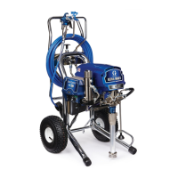
POWER SUPPLY CORD REPLACEMENT
Before doing this procedure, follow the Pressure
Relief Procedure Warning on page 24 to reduce
the risk of a fluid injection injury , splashing in the
eyes or on the skin, injury from moving parts, or
electric shock.
Unplug the sprayer!
WARNING
Refer to Fig 26–1.
1. Remove the pressure control cover
.
2.
Disconnect
the power supply cord lead from the ON/
OFF
switch (303), the white wire going
to the bridge
(308), and the green wire to the grounding screw
(343)
and lockwasher (327).
3. Loosen the strain relief bushing (328). Remove the
power
supply cord (31
1).
4.
Install
the new cord (31
1) in
the reverse order of dis
-
assembly.
5. Reinstall
the pressure control cover
.
311
Fig 26–1
328
343,327
303
308
ON/OFF
SWITCH
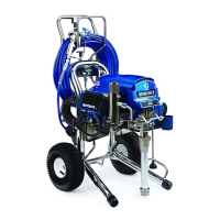
REPLACEMENT
Before doing this procedure, follow the Pressure
Relief Procedure Warning on page 24 to reduce
the risk of a fluid injection injury , splashing in the
eyes or on the skin, injury from moving parts, or
electric shock.
Unplug the sprayer!
WARNING
Refer to Fig 26–2 except where noted.
1. Remove the pressure control cover
.
2.
Use
a needle nose pliers to disconnect the upper
ter
-
minal
wire from
the microswitch (302) for ease in re
-
moving
the ON/OFF switch (303). Refer to Fig 26–1.
3.
Use
pliers to disconnect the two black wires from the
ON/OFF
switch (303). Refer to Fig 26–1.
4. Use a 5/8 in. socket wrench to loosen and remove
the nut and rubber boot (304) from the top of the
pressure control box. Remove the switch guard
(305).
5.
Remove the ON/OFF switch.
6.
Install
the new switch so the internal tab of the anti–
rotation ring (W) engages with the vertical groove in
the threads of the switch, and the external tab en-
gages
with the blind hole (D) of
the pressure control
box.
7.
Install the switch guard (305), aligning the internal
tab
with the groove in the threads.
8.
Powder the inside of the rubber boot (304) with tal-
cum,
then shake excess out of boot.
9.
Install the nut and rubber boot and tighten.
10. Reconnect
the wires to the ON/OFF switch (303)
and
reconnect
the wire to the microswitch (302).
11.
Reinstall the pressure control cover
.
302
D
W
305
303
Fig 26–2
 Loading...