32
307–785
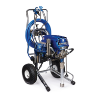
BEARING
HOUSING &
CONNECTING ROD REPLACEMENT
Before doing this procedure, follow the Pressure
Relief Procedure Warning on page 24 to reduce
the risk of a fluid injection injury , splashing in the
eyes
or in the skin, injury from moving parts or elec
-
tric
shock.
Unplug the sprayer!
WARNING
Fig 34–1
69
67
23
25
24
49
42
43
76
E
TORQUE
T
O
175 IN–LB
(19 N.M)
70
47
68
B
C
F
40
P
ACKING WITH
BEARING GREASE
OIL
NOTE: Stop
the sprayer at the bottom of its stroke to get
the crank (E) in its lowest position.To lower the
crank
manually
, carefully rotate the blades of the
fan
with a screwdriver
.
1. Remove the front cover (49). Hold a wrench on the
pump intake valve and unscrew the pump suction
tube.
Disconnect the short hose (70) from the pump.
2.
Push up the retaining spring (42). Push the pin (43)
out the rear
.
3.
Loosen the pump jam nut (47). Unscrew the dis-
placement pump (76).
4. Remove the four screws (25) and lockwashers (23)
from
the bearing housing (69).
5. Lightly
tap the lower rear of the bearing housing (69)
with
a plastic mallet to loosen it from the drive hous
-
ing
(67). Pull the bearing housing and the connecting
rod
assembly (68) straight of
f the drive housing.
6. Remove the pail bracket assembly (F) and reinstall
it
on the new bearing housing.
7. Inspect
the crank (E) for excessive
wear and replace
parts as needed. Evenly lubricate the inside of the
bronze
bearing (B) with high quality motor oil. Liber
-
ally
pack the roller bearing (C) with bearing grease.
8. Assemble
the connecting rod (68)
and bearing hous
-
ing (69).
9. Clean the mating surfaces of the bearing and drive
housings.
10. Align
the connecting rod with the crank (E) and care
-
fully
align the locating pins in the drive housing with
the
holes in the bearing housing (69). Push the bear
-
ing housing onto the drive housing or tap it into place
with
a plastic mallet.
CAUTION
DO
NOT use the bearing housing screws (25) to try
to
align or seat the
bearing housing; the bearing and
drive
housing will not align properly and will result in
premature
bearing wear
.
11. Install the screws (25) and lockwashers (23) in the
bearing housing. T ighten the screws evenly to
175
in–lb (19 N.m).
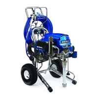
Fig 34–2
68
FACE
OF
BEARING
HOUSING
47
TORQUE TO
70 ft–lb
(95 N.M)
42
43
69
12. Screw
the displacement pump 3/4 of the way into the
bearing
housing (69). Hold the pin (43) up to the pin
hole in the connecting rod (68). Screw in the pump
until the pin slides easily into the hole. Back of f the
pump until the top threads of the pump cylinder are
flush
with
the face of the bearing housing and the out
-
let adapter (A) is facing back. Push the retaining
spring (42) into the groove all the way around the
connecting
rod.
T
ighten the locknut (47) very tight –
about
70 ft–lb (95 N.m) –
with a 2 in. open end wrench
and
a light hammer
.
See Fig 34–2.
WARNING
Be sure the retaining spring (42) is firmly in the
groove all the way around, to prevent the pin (43)
from
working loose due to vibration.
See Fig 34–2.
If the pin works loose, it or other parts could break
off
due to the force of the pump action. These parts
could
be projected through the air and result in seri
-
ous
bodily injury or property damage, including dam
-
age
to the pump connecting rod or bearing housing.
13. Install
the front cover (49). Connect the suction tube
(86)
and short hose (70) to the pump.
See Fig 34–1.
 Loading...