SETUP
1.
Connect Hose and Gun (Refer
to Fig 1.1
a.
Remove
the plastic cap plug from the filter
outlet nipple and screw the 50 ft (15.2 m) fluid
hose onto the nipple.
b. Connect the whip hose between the fluid hose
and the gun inlet connection.
c. Don’t use thread sealant, and don’t install the
spray tip yet!
2. Two Gun Hookup.
(Refer to Fig 1.1 Remove the
plug from the tee which holds the fluid filter to the
sprayer and install an accessory l/4 npt ball valve.
Connect an accessory hose and gun to the ball
valve.
CAUTION
To avoid damaging the pressure control, which
may result in poor equipment performance and
component damage, follow these precautions:
1. Always use nylon spray hose of at least
50 ft (15.2 m) long.
2. Never use a wire braid hose as it is too rigid
to act as a pulsation dampener.
3. Never install any shutoff device between
the filter and the main hose. See Fig 2.
4. Always use the main filter outlet for one-
gun operation. Never plug this outlet.
3. Fill Packing Nut/Wet-Cup (See
Fig 2.1
Fill the packing nut/wet-cup l/3 full with Grace
Throat Seal Liquid (TSL), supplied.
4. Check Electrical Service
a. Be sure the electrical service is 120 V,
60 HzAC, 15 Amp (minimum) and that the
outlet you use is properly grounded.
”
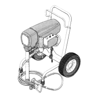
b. Use an extension cord which has 3 wires of a
Fig
i-MAlN FLUID HOSE
minimum 12 gauge size, and a maximum of
150 ft (45 m) long. Longer lengths may affect
sprayer performance.
5. Plug in the Sprayer
a.
Be sure the ON/OFF switch is OFF. Refer to
Fig 3.
b. Plug the power supply cord into a grounded
electrical outlet that is at least 20 ft (6 m) away
from the spray area to reduce the chance of a
spark igniting the spray vapors.
c. Do not remove the third prong of the power
supply cord plug, which is the grounding
prong, and do not use an adapter.
Fig 3
6. Flush the pump
to remove the No. 10 motor oil
which was left in to protect pump parts after fac-
tory testing.
a.
Before using water-base paint,
flush with
mineral spirits followed by soapy water, and
b. Stir the paint to dissolve pigments.
then a clean water flush.
7. Prepare the paint
according to the manufacturer’s
recommendations.
a.
Remove any skin that may have formed.
b.
Before using oil-base paint,
flush with mineral
spirits only.
c. See ‘*Flushing Guidelines”
on page 12 for
flushing procedure.
c. Strain the paint through a fine nylon mesh bag
(available at most paint dealers) to remove par-
ticles that could clog the filter or spray tip.
This
is probably the most important step toward
trouble-free spray painting.
307-643
9
 Loading...