18
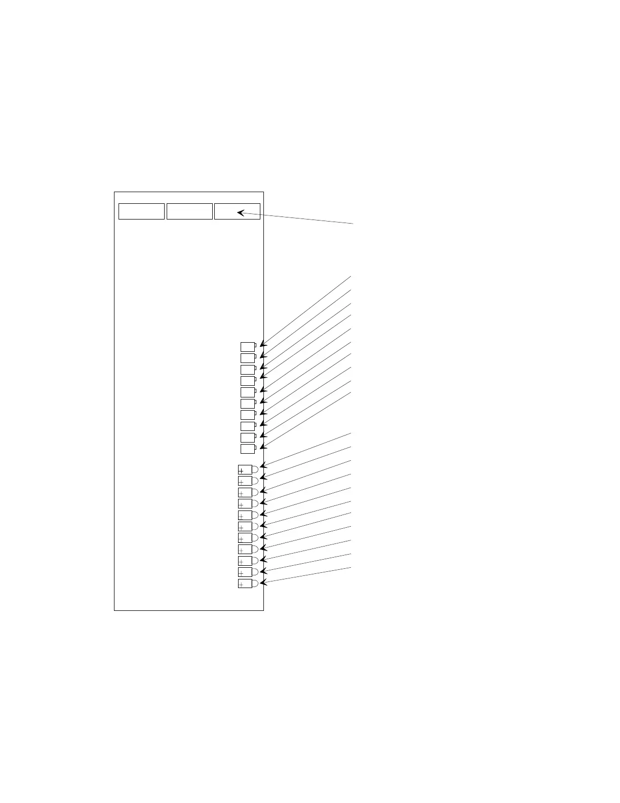
LD1 LD2 LD3 LD4 LD5 LD6 LD7 LD8 LD9 LD10 LD11
P1 P2 P3 P4 P5 P6 P7 P8 P9 P10
Offset
Gain
Minimum Speed
Maximum Speed
Maximum Ext. Speed (opt)
Overload
Current Limit
I Compensation
Walking Frequency
Volts/Hertz
Ready (yellow)
At Speed (yellow)
Run (green)
Temperature (green)
Fault (red)
Overload Indicator (red)
Overcurrent Indicator (red)
Overvoltage Indicator (red)
Undervoltage Indicator (red)
Phase Loss Indicator (red)
Ground Fault Indicator (red)
Dip Switches
CONTROL CHIP BOARD
Showing Location of Dip Switches, Potentiometers and LEDs
 Loading...