32
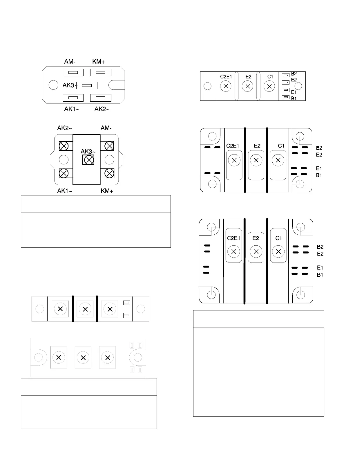
Meter Leads Resistance Reading
Positive Negative (ohms)
C1 C2,E1 >10,000
C2,E1 C1 <1,000
C2,E1 E2 >10,000
E2 C2,E1 <1,000
B2 E2 <1,000
E2 B2 <1,000
B1 E1 <1,000
E1 B1 <1,000
B1 C1 <1,000
C1 B1 >10,000
B2 C2,E1 <1,000
C2,E1 B2 >10,000
FREE-WHEELING DIODE MODULEFREE-WHEELING DIODE MODULE
FREE-WHEELING DIODE MODULEFREE-WHEELING DIODE MODULE
FREE-WHEELING DIODE MODULE
Free-wheeling Diode, 7.5 through 53 amp
1
Meter Lead Resistance Reading
Positive Negative (ohms)
AM- AK1~, AK2~, AK3~ <1,000
KM+ AK1~, AK2~, AK3~ >10,000
AK1~, AK2~, AK3~ AM- >10,000
AK1~, AK2~, AK3~ KM+ <1,000
OUTPUT DIODE BRIDGE MODULEOUTPUT DIODE BRIDGE MODULE
OUTPUT DIODE BRIDGE MODULEOUTPUT DIODE BRIDGE MODULE
OUTPUT DIODE BRIDGE MODULE
Output Diode Bridge, 7.5 through 34 amp
1
Output Diode Bridge, 40 through 100 amp
1
Meter Lead Resistance Reading
Positive Negative (ohms)
A1 K1, K2 <1,000
K1,K2 A1 >10,000
K1 A2 >10,000
A2 A1,K2 <1,000
Free-wheeling Diode, 65 through 100 amp
1
CONDUCTION/COMMUTATIONCONDUCTION/COMMUTATION
CONDUCTION/COMMUTATIONCONDUCTION/COMMUTATION
CONDUCTION/COMMUTATION
TRANSISTOR MODULETRANSISTOR MODULE
TRANSISTOR MODULETRANSISTOR MODULE
TRANSISTOR MODULE
Conduction/Commutation Transistor Module,
7.5 through 28 amp
1
Conduction/Commutation Transistor Module,
34 through 53 amp
1
Conduction/Commutation Transistor Module,
65 through 100 amp
1
1
Refer to the “Output Drive Current” rating on the
plastic cover over control board for this value.
K1K2 A1 A2
K1K2 K1 A2
A1
 Loading...